Are you interested in PWM drivers using MOSFETs? In this article, I explain how they work, how to choose the components, and how to build a PWM controller or driver using a MOSFET (Metal-Oxide-Semiconductor Field-Effect Transistor).
First, we’ll look at a bit of theory (I promise it’ll be brief and understandable), just enough to help you understand what we’re going to do, without simply building the circuit without knowing what you’re doing or why.
Next, we’ll look at a practical example involving a fan, where we’ll control its speed using all tests and measurements.
If at any point you get stuck or would like further information, you’ll find links to a number of additional posts at the end of the article where you can learn much more and find answers to your questions.
I’ll try, as on other occasions, to ensure that it isn’t just a ‘recipe’ what you need to do to set up the circuit. I'll try to make it an article that adds value and allows you to learn easily.
If all you want is a quick guide to building the circuit, without knowing what you’re doing or how it works, This article isn't for you.
Contents
- 1 How does a PWM driver with a MOSFET transistor work?
- 2 Selecting the MOSFET for our PWM driver
- 3 Requirements for our MOSFET PWM circuit
- 4 Component selection
- 5 Construction of a PWM driver using a MOSFET
- 6 Testing and measurement of the PWM driver circuit with a MOSFET
- 7 The difference between a PWM driver using a MOSFET and one using a BJT
- 8 Practical video on the PWM driver circuit using a MOSFET
- 9 Laboratory equipment I used in the video and which I recommend
- 10 What next?
How does a PWM driver with a MOSFET transistor work?
A PWM (Pulse Width Modulation) controller using a MOSFET is commonly used to control a wide range of devices: fans, LEDs, other transistors and almost any type of load.
It is really nothing more than a MOSFET that acts as a switch, opening and closing in a specific pattern, in time with a microprocessor, to generate a signal that controls the fan.
The reason we need this circuit is very simple: our controller alone is not capable of generating a signal with the power required to run a fan.
The vast majority of microcontrollers are capable of supplying between 6mA and 50mA through their pins, but our fan requires more power to operate (a standard 5V 40mm fan may require around 150–200mA).
If we were to draw the power required to run a fan from the microprocessor—no matter how small—the microcontroller would, in many cases, be damaged, and in others, it would simply stop working.
Even if the microcontroller didn’t burn out or stop working, the fan wouldn’t turn because it wouldn’t have enough power.
Here is a basic description of how this circuit works:
PWM signal generator
The PWM signal generator is our Arduino, ESP8266, ESP32, Raspberry Pi or whatever else will control the fan via the circuit we are going to build.
The PWM controller generates an output signal that varies in pulse width (the duty cycle). The duty cycle determines the length of time during which the signal is at high level (on) compared with the time at low level (off).
The PWM signal acts as a control signal for the MOSFET transistor, allowing the speed of the fan (or any other load we are using, such as an LED or a motor) to be adjusted.
If these two concepts sound like Greek to you, don’t worry. Below, I’ve included two blog posts where you’ll find everything you need to know about what a PWM signal is and about load control using PWM.
Schematic diagram of PWM driver with MOSFET
A basic schematic might look like this for an N-Channel MOSFET:
Here’s another visualisation, in case you find this one easier:
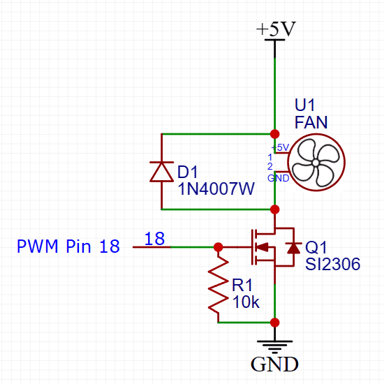
This is a basic example and specific component selection will depend on fan current, operating voltage and other system requirements.
The MOSFET acts as a switch controlled by a PWM signal.
The load we want to control (the fan, for example) is connected to the MOSFET and is powered through it. The fan speed is directly related to the duty cycle of the PWM signal. The higher the duty cycle, the higher the fan speed, and vice versa.
In addition, a resistor should almost always be added between the gate and pin 18 to control the turn-on speed and gate current.
The MOSFET transistor
Before we move on to selecting the components we’re going to use, it’s important that you understand the basics of how a MOSFET works.
I recommend you read the following article, where you’ll find everything you need.
Remember that this circuit is really nothing more than a MOSFET acting as a switch, opening and closing in a specific pattern, in time with a microprocessor, to generate a PWM signal that controls the fan.
Selecting the MOSFET for our PWM driver
Now that you know the basics about MOSFETs thanks to the article you’ve just read (haven’t read it yet? Well, go back three lines, click on the link and read the article!), you can start applying what you’ve learnt to this circuit.
It is important to select a MOSFET that can handle the fan current and dissipate the generated power. In addition, the PWM controller must be able to provide the necessary signal to control the MOSFET.
If the MOSFET is controlled by a microprocessor (operating at 3.3V or 5V), it is essential to use a MOSFET with logical level or ‘Logic Level’ MOSFET.
Logic-level MOSFETs or ‘Logic Level‘ are designed to operate on an all-or-nothing basis between the drain and the source with a very low voltage signal (3.3V, 5V or sometimes less) on the door.
Remember, too, that a logic-level MOSFET or ‘Logic Level A MOSFET is either on or off. As there are no intermediate states, the design is optimised, and we avoid losses and overheating of the MOSFET.
Requirements for our MOSFET PWM circuit
Before moving on to the practical part, we have to define exactly what we want, with its requirements and operating parameters.
Above all, we will need to define:
- Vvoltage to which the fan is connected: We will use a 5V fan.
- Iintensity to the one the fan is connected to: We will use a 200mA fan nominal.
- The amplitude (voltage) of the PWM signal which we will use to control the driver: In our case 3.3V (the voltage of a Raspberry Pi, an ESP8266, an ESP32 and many other controllers).
- Frequency of the PWM signal: In our case, we will use 25Khzwhich is fairly standard.
Component selection
We will select the components based on the requirements we have defined.
We only need three components:
- A diode to prevent the reverse currents generated by the fan from damaging our circuit (or the microprocessor to which it is connected).
- A MOSFET transistorThe fan is a switch that regulates the power supply to the fan.
- A resistancewhich ‘power off’ the MOSFET transistor when we remove the voltage from its gate.
We will also need a 5V fan of the kind used to cool Raspberry Pi and similar things.
We will use a 40x40mm fan two-wire (positive and negative only) with a theoretical maximum consumption of 200mA.
Diode selection

The diode is not much of a secret. We can use almost any diode. We only have to make sure that it supports the necessary current (which is very little, we can assume a few mA, because it would only be the current that the fan is able to generate).
In our case we are going to use a 1N4001 or 1N4007 (they are almost the same, for the purposes of what we care about here), although you can use many other similar diodes.
This 1N4001 diode is ubiquitous and can be found in many circuits. It is probably the most widely used diode in the world (this or its Chinese equivalents).
Selection of the MOSFET
Choosing a MOSFET isn't particularly difficult either.
We are going to use a transistor that is:
- Very easy to find
- Very cheap
- Sturdy and able to withstand a lot of rough handling
Selecting a MOSFET is slightly more complicated than selecting a BJT, as there are more factors to take into account, but not by much.
We need to make sure that:
- Let there be a MOSFET of type ‘logic level’.
- Have a Vgs 3.3V or less (preferably below 2.5V)
- Get an Rds(on) as low as possible.
- Ensure that the source-drain current is at least 200mA, which is the current drawn by our fan.
- Ensure there is a gate flow (IG) that our microcontroller is capable of providing.
By the way, you might be wondering… And how do I know if a MOSFET is suitable for use with 3.3V (or, better still, 3V) logic levels?:
Well, the simplest and most straightforward thing to do is to check whether the MOSFET datasheet specifies a value for Rds when Vgs is ≤ 3.0 V. This may appear in two places on the datasheet: as a value written in black text on a white background, or in the graph of Rds(On)–Vgs which include all the datasheets.
What I usually do is look for a MOSFET that specifies a Rds(on) @ VGS =2.5V
To read the above, replace the @ symbol with ‘when’ (this indicates which VGS, or when VGS «OK», it has that Rds(on)).
To get straight to the point, let’s choose our MOSFET:
I’ll start by saying that:
- I’m going to use an SMD MOSFET (for the reasons I mentioned earlier, mainly because there are so few logic-level MOSFETs available in this size) normal).
- I’m going to simply choose a transistor from those I already have in my lab, rather than trying to find one ‘the perfect transistor’.
I am looking through the MOSFETs I have to find only those that are Canal-N and shortlists the following: Si2300, Si2306, Si2320.
And why have I shortlisted these in particular? Because they’re from the same manufacturer (Vishay), so I hope that makes it easier for you to compare them and spot the differences, as their datasheets are quite similar in format.
When comparing transistors from different manufacturers, it can be a little more difficult at first because their datasheets may not show the same values or tables, or because the abbreviations used for the values may differ.
You can find the datasheets for the three MOSFETs here:
- Vishay Si2300 MOSFET datasheet
- MOSFET transistor datasheet Vishay Si2306
- MOSFET transistor datasheet Vishay Si2320
I have created the following table, containing the values we are interested in, to make it easier for us to compare them:
| Si2300 | Si2306 | Si2320 | |
|---|---|---|---|
| You | 20A | 30A | 20A |
| Id | 3.6A | 2.8A @ Vgs = 4.5V | 2.4A @ Vgs = 2.5V |
| VGS(th) | 1.5V | 1V | 0.65V |
| Maximum Vgs | ±12V | ±20V | ±8V |
| Rds(on) | 0.085(Ω) at VGS = 2.5 V | 0.094(Ω) @ VGS = 4.5 V | 0.085(Ω) @ VGS = 2.5 V, ID = 3.1A |
The first thing I notice is that the Si2306 shows in its data a Vgs minimum of 4.5V, which already indicates that the manufacturer does not recommend using it at lower voltages.
A second clue comes from the fact that, in the datasheet, the «On-Resistance vs. Gate-to-Source Voltage» graph only shows values of Rds(on) from around 3.8V, which already tells us that it is not suitable for use below that voltage.
Down with the Si2306!
There isn't much difference between the Si2300 and the Si2320, as far as we're concerned. Really either one would do. My choice will come down to something very practical and mundane: I’ll go for whichever one I have more of.
Selecting the resistor

The resistance between the gate and the source of a MOSFET is used to limit the current flowing into and out of the gate, helping to prevent overly rapid transitions that could generate electrical noise and consume more energy than necessary. This resistor is commonly known as a gate resistor (RG).
As mentioned earlier, it is also used to discharge the internal capacitor.
The choice of gate valve depends on several factors:
- Desired ascent/descent time (trise/tfailure): If you want the gate to charge and discharge quickly in order to achieve shorter switching times, you can opt for a lower resistance. However, you must take into account the current limitations of the control power supply.
- Maximum gate flow (IG(max)): Make sure that the resistor does not allow more current than necessary to flow through the gate, as this could damage the control device.
- Control unit capacity: Check the drive capability of the control source (for example, the output capability of a microcontroller pin) to supply the current required to charge and discharge the gate via the selected resistor.
The basic formula for calculating gate resistance (RG) is:
RG = ( trise / tfailure ) / (0.35 × IG(max))
Where:
- trise/tfailure is the desired ascent and descent time.
- IG(max) is the maximum current through the gate.
The constant 0.35 in the denominator is based on the assumption that the rise/fall time is approximately 35% of the final value. You can adjust this value to suit your specific requirements.
As you can see, the choice of gate valve rating depends on many factors and allows for values within very wide ranges.
In our case, we are going to use a 10 kΩ resistor and take some measurements to see if we need to adjust it:
- We will measure the current at the gate
- We will measure the signal's rise and fall times using the oscilloscope
It is important to note that, in some cases, it may be useful to add a resistor in series with the MOSFET gate to limit the peak current during switching and improve the system’s resilience to current transients.
This additional resistor may be referred to as a «gate resistor» in some contexts, and its value is selected in a similar way.
Construction of a PWM driver using a MOSFET
Now for the best bit: building the PWM driver using a MOSFET transistor.
It’s a very simple circuit, made up of very cheap components that are relatively easy to get hold of. What’s more, it’s very easy to assemble, even for someone who’s just starting out or working on their first project.
Let’s start by putting it together and quickly checking that it works properly.
In the next section, once we have it set up, we will look at the tests and measurements we can do with it and we are sure to learn a lot.
There are several options available for track riding. The main ones are:
- Breadboard
- Perfboard or protoboard
- Outdoor mounting
- Custom printed circuit board
We also have the option of assembling with traditional "large" components (through–hole) or with tiny surface mounted components (SMD).
As we are going to be using SMD components in this case, for the reasons we have already mentioned, we will build it directly onto a breadboard, which is the simplest way to assemble this type of circuit.
Surface-mount assembly is not an option when dealing with SMD components. Their leads are extremely fragile and cannot withstand any mechanical stress whatsoever.
It’s such a simple circuit that, in my opinion, it’s not worth having a custom printed circuit board made.
Soldering SMD components onto a breadboard
Are you daunted by assembling SMD components? You shouldn’t be. I love them, and I actually find it easier to assemble SMD circuits.
What’s more, I can keep a whole bunch of SMD components in a very small space and for very little money (yes, they’re much cheaper) so I can tackle loads of projects without having to keep ordering parts.
I’ll assemble the final circuit directly on a breadboard, aiming for a compact layout, though without making things unnecessarily difficult just to save a centimetre2.

If, after watching the video—which shows just how easy it is to solder this type of component—you’re still nervous about soldering SMD components, you can always use a small adapter board like these.
Before assembling the circuit on a perfboard, I’ll put together a quick setup on a breadboard, which allows for quick changes so I can carry out the necessary tests and measurements.

So that I can plug it into the breadboard, I’ll solder it to a small adapter board.
As I don’t have a board of this type available for mounting an SOT32 (which is the package our MOSFET uses), I’m going to use one of these SOT89 adapters, even though it won’t be an exact fit.
You'll see that the MOSFET pins don't quite reach the pads on the board, but it doesn't matter – I'll extend them with a bit of extra solder.
You can also solder it onto a standard breadboard. It won't cost you much.
Our assembly on a breadboard
Although it’s a breadboard setup, I’ve soldered the Si2300 MOSFET transistor onto a small perf-board to make it easier to handle during the tests we’re going to carry out.
You can see it in detail in the photo below (you can click on it to enlarge it if you like).

This is the layout we’ll be following for the breadboard assembly. You can click on it to view a larger version, which should serve as a guide.
And this is what it will look like when it’s finished:
Our assembly on a perf-board

If you want to mount the driver on a perforated breadboard, you can follow the tutorial for the Mini HAT PWM for Raspberry Pi.
Although I wrote this with the Raspberry Pi in mind, you can use it for any other project.
Testing and measurement of the PWM driver circuit with a MOSFET
Finally, the most interesting part (at least for me)! The tests and measurements.
We have already assembled the circuit and checked that it works. Now we can see for ourselves many of the points we have discussed in theory.
- MOSFET gate current
- Current in the drain-source channel
- Minimum duty cycle
- MOSFET temperature. Have we got everything right, or is the MOSFET heating up like a heater?
Using the data from these measurements, we will be able to optimise the circuit using real-world data, if necessary, as some of the values have been assumed or estimated.
MOSFET gate current
As we mentioned earlier, the MOSFET is an extremely efficient component that consumes very little power.
We connect the multimeter, set to current measurement mode, between the PWM signal input and the MOSFET gate, and power up the circuit.
In this case, you are using about 328 µA, without optimising fuel consumption. We could reduce the power consumption by adding a current-limiting resistor to the gate, but as this isn't a battery-powered circuit and the power consumption is so low, I haven't bothered to add one.
Current in the drain-source channel
We connect the multimeter, set to current measurement mode, between the voltmeter and its positive supply terminal, and take a reading.
Nothing out of the ordinary: 140 mA, which is roughly equivalent to the power consumption of the fan.
Minimum duty cycle for fan movement
This point is taken from the article ‘PWM Driver with a BJT Transistor’, but I’m including it here as well because the explanation is also relevant when using a MOSFET to control the fan.
The results aren't quite what you'll see below (you can see them in the video), but I want to run a few more tests before updating them, because something doesn't quite add up…
The great advantage of using a PWM signal is that we can turn the fan at any speed we wantbetween the minimum allowed by the fan (below this minimum, which depends on each fan, it will simply stop, while it tries to rotate) and the maximum corresponding to its nominal supply voltage (minus any losses generated by our circuit).
This means that we cannot lower the duty cycle to, for example, 1% because the fan will not have enough energy to move.
This minimum duty cycle is very important to know, in practical applications, to avoid trying to send PWM signals below the minimum.
Note that if we send the fan PWM signals below the minimum, the fan will not move, but it will heat up because it will have to dissipate the energy that we are sending it in the form of heat..
This is important whenever we control a fan via PWM, we have to avoid at all costs trying to send PWM signals below the minimum that will allow it to move smoothly.
Measuring the minimum duty cycle for the fan to move will not be difficult, but a little more cumbersome due to the use of laboratory instruments other than the multimeter.
To generate the PWM signal I am going to use a programmable digital function generator and I'm going to join it to an oscilloscopeto make sure that the PWM signal I am measuring is correct and to avoid errors.
The best thing to do, as it is very dynamic, is to watch the tests in the video, but I can tell you in advance:
- If the fan is moving, we can lower the duty cycle to 60% without it stopping.
- If the fan is stopped, the duty cycle must be increased to 100% to start the fan (to overcome the inertia and 'start-up'.). Once it is in motion we can move down to the 60%.
It is very important for you to understand and keep in mind that these work cycles depend on the individual fan and can vary greatly from one to another.
I will provide further details on this point as I carry out more tests with this and other fans (and with different drivers and microcontrollers, just in case there are any differences).
MOSFET temperature
As always when building a circuit, especially if we have designed it ourselves, we must ensure that its operating temperature is correct and always under control.
At the very least, you should touch it with your finger and check that it isn’t getting too hot (at least not what we would consider to be too hot).
Here, to avoid the subjectivity from our finger, I'm going to use a thermal camera to find out its actual temperature in various situations.
In the image below, you can see our circuit after it has been running for at least 30 minutes.
As you can see, the MOSFET's temperature is «as cold as ice». In other words, room temperature.
You can see the fan running at 31.1°C, and in its bottom-left corner is the MOSFET, which is at the same temperature as its surroundings.
Incidentally, the fan’s temperature doesn’t vary much depending on the PWM signal. It remains between 26°C and 31°C at all times (with the current ambient temperature at 24.9°C).
I haven’t included these steps in the video for two reasons: because there’s nothing interesting to say about them, and because I forgot to film them before I’d finished editing the video (and yes, if there had been anything interesting to say, I would have re-edited it, even though it was already finished).
The difference between a PWM driver using a MOSFET and one using a BJT
The choice between a MOSFET (Metal-Oxide-Semiconductor Field-Effect Transistor) and a BJT (Bipolar Junction Transistor) in a switching circuit, such as PWM fan control, involves several key differences:
Operating Principle
- MOSFETs are voltage controlled devices, where the voltage between the gate and the source controls the current between the drain and the source.
- BJTs are current controlled devices, which means that the base current controls the current between the collector and the emitter.
Control Current
- In MOSFETs, the gate current, or gate, (Ig) is very small and is mainly used to charge or discharge the gate. The power consumed is mainly due to the charging and discharging of the gate capacitance.
- In BJTs, the base current (Ib) is essential to activate the transistor and control the collector current (Ic).
Energy Efficiency
- MOSFETs tend to be more energy efficient in high-frequency switching applications, as they have lower switching losses and require less control current.
- BJTs can have higher power losses due to the base current required for operation.
Switching Speed
- MOSFETs typically have faster switching times than BJTs, making them more suitable for high-frequency applications such as pulse width modulation (PWM) at high speeds.
- BJTs can have slower switching times compared to MOSFETs.
Temperature Sensitivity
- MOSFETs are less sensitive to temperature variations in terms of performance.
- Temperature can affect the gain (hfe) of the BJTs, which can influence their performance.
Overcurrent Protection
- MOSFETs are generally more robust in terms of overcurrent protection, as devices with thermal shutdown characteristics can be implemented.
- BJTs can be more susceptible to damage from overcurrent and overheating.
The choice between a BJT and a MOSFET depends on the specific application, switching requirements, desired power efficiency and other circuit design factors. In general, MOSFETs are more common in high-frequency switching applications and for controlling high-power devices, while BJTs are still suitable for certain low- and medium-power applications.
Practical video on the PWM driver circuit using a MOSFET
To round off this article, here is the video I’ve put together to accompany it:
Making these videos takes a lot of work. If you like the video don't forget to "Like" and subscribe to the channel. That's will motivate me to keep making more videos like this one.

Laboratory equipment I used in the video and which I recommend
👉 Thermal imaging camera VICTOR VC328B
👉 FeelTech Function Generator FY3200-24Mhz
👉 Rigol DS1054Z Oscilloscope at Amazon UK
What next?

I think we have covered in sufficient detail how it works, how to calculate it and how to build a PWM driver using a MOSFET transistor.
I’ll be adding to and improving this article over time. Do pop back every now and then to see what’s new.
If you liked this post, I suggest you read the following related articles, where you can find much more information on this exciting topic:
An excellent educational resource – I highly recommend it