
Do you want to, like me, reduce Raspberry Pi fan noise (or even eliminate it)? If so, here is the ultimate solution to our noise problems: the variable speed fan for Raspberry Pi. An easy and cheap solution (a couple of euros).
This tutorial is accompanied by a videoI'll leave it below, so that you can follow it very easily.
Following this tutorial, you will be able to build, with very few components, a small controller for the Raspberry Pi to regulate the speed of its fan depending on its temperature and we will complete it with a small Python program to do the monitoring and control work.
Whenever I write a blog post, my top priority is always to that provides value for the readerthat actually provides knowledge. Not write empty articles that just skim over a topic with information that is already all over the internet.
Why have I written this tutorial on how to set up a temperature-controlled variable speed Raspberry fan, when there are already many on the internet?
Because the articles I found seemed too biased, or didn't seem to explain the basics well, in a way that I didn't think they could. understandable.
In addition, I have found that most tutorials for implementing temperature-based PWM speed control on the Raspberry Pi THEY DON'T DO IT WELL (I will explain why later).
This article (and the other articles it links to, which I have written in support of this tutorial), attempt to cover the topic in depth but understandable, trying to that anyone can easily understand it just by reading the blog and with no prior preparation..
I hope you enjoy it!
It seems unbelievable how long it took, both hardware and software, until everything worked perfectly.
The fact that it has taken longer than expected has not discouraged me at all, quite the contrary. This means that the subject is not so simple and that this article will have a lot of value.
The truth is that I have learned a lot along the way. I didn't expect that such an apparently simple subject would give me so many headaches.
I have several Raspberry Pi running at home for different tasks. They are small devices, with low power consumption and very stable in their operation (they can be running continuously for months without needing a reboot).
I have used the original Raspberry Pi (the v1), the Raspberry Pi 2, the Raspberry Pi 3 and its "in-between" versions (with the "B" or "+" added) and temperature has never been an issue. They have all worked great for years with no heat problems.
The last one I added, a Raspberry Pi 4, has much more power and performance than the previous ones and that means that it has some cooling requirements far above those of their predecessorsCan a Raspberry Pi 4 be used without a fan? Yes, but it is not advisable to run a Raspberry Pi 4 without a fan to refrigerate it.
It is assumed that if we put a Raspberry Pi 4 it is because we need its power in some moments (if not, why use a Raspberry Pi 4?, better to put one of the previous models, which are cheaper and consume less) and in this case to provide it with a cooling fan is almost indispensable.
The disadvantage of adding a fan to the Raspberry Pi 4 is that ceases to be a silent 100% device to become a minor nuisance (especially in a quiet bedroom or office).
How loud is a Raspberry Pi 4?
The Raspberry Pi 4 itself does not make noisehas no moving parts, what makes noise is its fan…
The noise level of a 5V fan for a Raspberry Pi 4 can vary depending on the model and make of the fan, as well as its design and build quality. However, in general, small 5V fans tend to be quite quiet, especially if powered at 3.3V (yes, 5V fans powered at 3.3V so they spin slower and make less noise).
The noise level of a fan is generally measured in decibels (dB), and small 5V fans designed for Raspberry Pi often have a noise level of around 20 to 30 dB. This is relatively quiet and should not be annoying in most situations.
It is important to note that there are some factors that can influence the noise level, such as the speed at which the fan operates and the quality of the fan's bearing. If you need particularly quiet operation, you can opt for fans with high quality bearings, such as fluid bearings or ball bearings, which tend to generate less noise than simpler bearings.
In any case, if noise is a concern for you, you can look for fans designed specifically for low-noise applications or those with speed control options to adjust fan speed as needed, which can help you maintain a balance between temperature and noise.
Taking all of the above into account, we can say that the fan noise of a Raspberry Pi 4, once we have chosen the fan (better or worse, higher or lower quality) and connected it, will always spin at the same speed, cool in the same way and make the same noise..
If we want to reduce the noise, taking advantage of the fan always running at maximum (in fact, we don't even need the fan to be always running) the solution is to have a variable speed fan for Raspberry Pi.
Why should I put a fan on a Raspberry Pi 4?
It is good to put a fan on a Raspberry Pi 4 or other similar electronic devices for several reasons:
- Refrigeration: The Raspberry Pi 4 can generate heat, especially when running CPU or GPU intensive applications. A fan helps dissipate that heat more efficiently, which prevents the device's temperature from rising too high. Operating at lower temperatures can help prevent overheating, which can negatively affect the Raspberry Pi's performance and lifespan.
- Increased performance and stability: Keeping the temperature of the CPU and other components at a lower temperature can allow the Raspberry Pi to run more steadily and without slowdowns caused by overheating.
- Damage prevention: Excessive heat can damage electronic components over time. A fan can extend the life of the Raspberry Pi and prevent long-term damage.
- Consistent performance under intensive workloads: If you plan to use your Raspberry Pi for intensive tasks, such as game emulation, machine learning or video transcoding, a fan can be essential to maintain consistent performance and avoid thermal throttling.
- Reduced fan speed and noise: You don't need the fan to be at full speed all the time. You can set the fan to run only when the temperature reaches a certain threshold, which helps reduce noise and power consumption.
All of the above confirms what we suspected, putting a fan on a Raspberry Pi 4 is a good idea if you plan to use it for tasks that generate heat or in environments where the ambient temperature is high. It will help keep the Raspberry Pi running efficiently and prolong its lifespan by keeping temperatures under control.
And since we're putting a fan, we'd better put a variable speed fan for Raspberry Pi.
What is the quietest Raspberry Pi 4 fan?

I can tell you, without fear of contradiction, that the quietest fan is the fan that is switched off..
We can put better quality fans, lower voltage, graphene or Kryptonite bearings, but all of them, without exception, make noise.
If we want a fan to be silent, the best way is to turn it off when it is not necessary and put it to the minimum speed to keep the temperature of the Raspberry Pi 4 under control (it is not necessary that it is always "always on").as cold as possible").
However, if I have something to tell you: As a general rule, Raspberry 4 fans are very small (usually 40mm) and this means that they have to rotate very fast in order to provide a significant amount of air.
To move the same amount of air, a smaller fan (such as a 40 mm fan) must spin approximately 9 times faster than a larger fan (such as a 120 mm fan).
The speed ratio is calculated as follows:

Where:
- Dlarge fanis the diameter of the large fan (in this case 120 mm).
- Dsmall fanis the diameter of the small fan (in this case 40 mm).
If we substitute the values in the formula:

In summary, if we want to have the quietest possible fan, we should look at:
- Switch off the fan when it is not needed
- Adjust the fan speed to the minimum necessary at any given time
- Mount the larger fan that it is possible for us to
The fan for the Raspberry Pi 4
For our variable speed fan we are going to use a small 5V DC fan (if you're curious, we're going to use a 5V DC fan), click here to see the different types of fans that can be used on a Raspberry).

This is a simple fan that only has a DC motor that moves the blades. In this case, its speed will depend on the voltage we feed it with.
It has only two wires, the positive and negative power wires (which, by the way, you can connect backwards and the fan will rotate in the opposite direction).
If you want more details about why I have chosen this type of fan, why I have decided to vary its speed via PWM and many more details about PWM fan speed control, you will like the following blog article:
Although it is not obligatory to read this article, it is interesting to do so, as it lays the groundwork for what we will see below.
If you find that you get lost in the following explanations, come back here and read the article "Controlling the speed of a fan with PWM".
How do we regulate the fan speed of the Raspberry Pi 4?
We are going to do this by generating a PWM signal and amplifying it, with a small circuit, as the Raspberry Pi cannot directly supply a PWM signal with the power needed to move a fan.
To do this, we are going to write a small Python program that generates a PWM signal that has a Duty cycle variable depending on how fast you need the fan to spin to cool the Raspberry Pi 4.
We will make the Raspberry Pi 4 run this program automatically and every 15 seconds (configurable) the program will modify, if necessary, the PWM signal to increase or decrease the fan speed.
This programme shall have a minimum value of Duty cycle PWM signal to ensure that the fan always moves and never blocks because it does not have enough energy to overcome inertia and start moving.
In addition, we are going to write a small auxiliary program that will allow us to find out what is the Minimum duty cycle for the fan to start and what is the Minimum duty cycle so that the fan does not stop, once it is in motion (both Working cycles need not be the same, and they will not be).
For our PWM signal we will use the following parameters:
- Amplitude: 3.3V
- Duty cycleIt will go from the minimum that allows the fan to start (or not to stop, if it is already moving) to 100%.
- Frequency: 25Khz
Just by feeding the fan with this PWM signal, instead of connecting it directly to 5V (or 3.3V), we will have a variable speed fan on the Raspberry Pi.
The PWM signal amplifier electronic circuit

The normal power consumption of small 5V 40x40mm fans is approximately 150mA.
The Raspberry Pi can only safely provide 16mA, according to the official Raspberry Pi documentation (and 50mA simultaneously, adding up all its pins).
We are going to add a very simple electronic circuit to our Raspberry Pi 4, with a transistor that, with this small control signal, of limited intensity, is capable of generating an equal signal but that can reach a minimum of 200 or 300mA.
Such circuits are often referred to as "drivers.
There are two main ways of doing it (very similar) and I'll leave you with both, so you can choose the one you prefer (although my recommendation is to use the MOSFET version).
PWM driver with BJT transistor
This is the schematic of our driver with BJT transistor:
Unless you already have the components (especially the BJT transistor), I recommend you to build the PWM driver with MOSFET transistor. below.
This is the prototype of the BJT transistor driver I built for testing.
As you can see, the plate is very dirty (let's say it is very dirty). "worked".), due to the large number of tests I did with different variations:
Different transistors in configuration high-side y low-sidedifferent resistor values, many measurements, etc...
Even using normal components "through hole". (not surface mount), as you can see it was a very compact size, so you can fit it inside the Raspberry Pi 4 case.
In the following article you have all the information on the PWM driver with BJT transistor:
PWM driver with MOSFET transistor
This is the type of driver I recommend you build.. Among other advantages, it is more efficient in operation than the BJT transistor driver and it heats up less.
This is the schematic of our PWM signal driver with MOSFET transistor:
As you can see, it is very similar to the BJT transistor driver we saw before.
In the following article you have all the information on the PWM driver with transistor BJT:
Variable speed fan control software for the Raspberry Pi 4
Here is the video I have prepared to make it easier for you to follow this tutorial. I recommend that you watch it as you read it.
Making these videos takes a lot of work. If you like the video don't forget to "Like" and subscribe to the channel. That's will motivate me to keep making more videos like this one.

Although what we are about to do is very simple and shouldn't cause any problems, the risk is always there, so I recommend that you make a backup copy (I suggest you directly clone your Micro SD card before touching anything).
Generating a PWM signal with the Raspberry Pi 4
Generating PWM signal on the Raspberry Pi with Python is not difficult at all, but it is important to know how, because it is, either I am very wrong, or the vast majority of information on the internet is wrong..
Here's why most of the tutorials for implementing temperature-based PWM speed control on the Raspberry Pi that I've seen on the internet have been for the following reasons THEY DON'T DO IT WELL.
Initially, I did this whole project with the RPi.GPIO library (which is the recommended one, and the one 99% people use on the internet) and I noticed some noises in the fan and very little smoothness in its operation.
I attributed the noises and poor running smoothness to the fact that it was not a good quality fan, but, by testing with the oscilloscope, I saw that something wasn't right...
The PWM signal generated was horrendous, full of noise, at a frequency that was not the one I had set and both the frequency and duty cycle values were very unstable.
The most curious thing was that the system worked and if I hadn't tested thoroughly with the oscilloscope I would never have known how bad it was turning out. Surely there are millions of systems like this 'functioning'. in the world without knowing the problems they have.
I did some research and found that the library RPi.GPIO does not generate the PWM signals by hardware, but by software. (even if you use a hardware pin), and worse, it has problems with signals over a few kilohertz.
Using a PWM signal with a frequency of 1Khz, for example, the system worked, but the fan made a noise, perfectly audible, that was worse than having it running at full power.
An additional important disadvantage is that when the PWM signal is generated by software, it is the CPU of the Raspberry Pi that does all the work (and it is a lot, because it has to be continuously attending and activating and deactivating the pin) so the CPU consumption can be high.
I am still documenting all this, testing, writing and recording videos so that I can explain it well. I will include the information shortly.
The solution was to use a different library, instead of the RPi.GPIO. One that supports hardware PWM signal generation.
There are a few projects (the fewest) that use some form of hardware PWM control, but most have problems or limitations.
- They are based on obsolete, or under-used, or unsupported projects such as wiringPi
- They need a running demon (like pigpio), which complicates installation and architecture.
Generating a hardware PWM signal with Raspberry Pi 4
You can generate a PWM signal on a pin of a Raspberry Pi 4, in a very easy way, using Python and the library ‘rpi-hardware-pwm‘.
The first thing to do is to prepare the Raspberry Pi to be able to use the two hardware PWM channels it has.
You have to edit the file /boot/config.txt and include the line dtoverlay=pwm-2chan
To do this, from the console run:
sudo nano /boot/config.txt
And after the last line beginning with dtoverlay (which is possibly annotated, with a pad ‘#’), includes the line:
dtoverlay=pwm-2chan
This will enable hardware PWM in the Default GPIO: GPIO_18 for PWM0 and GPIO_19 for PWM1.
If you want, you can use (instead of the previous line), the line:
dtoverlay=pwm-2chan,pin=12,func=4,pin2=13,func2=4
This will enable hardware PWM in the Alternative GPIOs: GPIO_12 for PWM0 and GPIO_13 for PWM1.
Now restart the Raspberry Pi, for the changes to take effect, with:
sudo reboot
When the Raspberry Pi starts up again, go back into the console and install the library rpi-hardware-pwm with:
sudo apt-get update
sudo pip3 install rpi-hardware-pwm
Test programme and calibration of the PWM signal for the specific fan
The Raspberry Pi is now ready to generate a hardware PWM signal.
Now we need a programme, which allows us to:
- Prove in an easy way that it does indeed work.
- Find out the minimum duty cycles so that our fan does not stall (each one is different).
For this I have created a very simple script, in the Python programming language, hardware_pwm_generator.pywhich allows us to call it with three parameters on the Raspberry Pi command line:
- 0 to use the channel PWM0 at GPIO_18 PWM0 and PWM1 at GPIO_19 (or PWM0 on GPIO_12 PWM0 and PWM1 on GPIO_13, if you have chosen the alternative pins in the file /boot/config.txt.
- The frequency in hertz. For example, 25000 for 25Khz.
- The duty cycle (a number between 0 and 100).
import sys
from rpi_hardware_pwm import HardwarePWM

def set_pwm(pwm_channel, frequency, duty_cycle):
    pwm = HardwarePWM(pwm_channel, frequency).
    pwm.start(duty_cycle)
    input("Press Enter to stop the PWM...")
    pwm.stop()

if __name__ == "__main__":
    if len(sys.argv) != 4:
        print("Usage: python pwm_generator.py   ")
        sys.exit(1)

    pwm_channel = int(sys.argv[1])
    frequency = float(sys.argv[2])
    duty_cycle = float(sys.argv[3])

    try:
        set_pwm(pwm_channel, frequency, duty_cycle)
    except KeyboardInterrupt:
        pass
Save this program in a file called "hardware_pwm_generator.py".
You can do this by running this line from the console:
sudo nano hardware_pwm_generator.py
You can run the program with the following command:
python hardware_pwm_generator.py .
Replaces:
- <canal_pwm> By the PWM channel you want to use (0 or 1). For example, a 0 to use PWM0 channel of GPIO_18.
- . By the frequency in Hertz that you want the PWM signal to have. For example, 25000 for 25Khz.
<work_cycle>by the duty cycle you want, e.g. "50" for a 50% duty cycle.
For example, to generate on PWM channel 0 (PWM0) on GPIO_18 a signal at 25Khz with a duty cycle of the 80%, you have to run on the console:
python hardware_pwm_generator.py 0 25000 80
To exit and stop the PWM, just press [Enter].
You can also interrupt and exit the programme with Ctrl-C. In this case the PWM signal will not stop.
The code is as follows:
Raspberry Pi CPU temperature readings
Let's see what we have to do to read the temperature of the CPU of the Raspberry Pi in a simple way, to go little by little and to be understandable. Later we will see how to modify the PWM signal based on the temperature.
To read the CPU temperature of a Raspberry Pi you can use the library psutil..
Make sure you have the library psutil. installed on your Raspberry Pi. You can install psutil with the following command:
sudo apt-get update
sudo pip install psutil
Now that we have the library installed, we can see the temperature by running the following line:
vcgencmd measure_temp
Here is a simple Python program that uses the psutil library to read the CPU temperature and prints it to the console every 5 seconds:
import psutil
import time

def get_cpu_temperature():
    try:
        temperature = psutil.sensors_temperatures()['cpu_thermal'][0].current
        return temperature
    except Exception as e:
        print(f "Error getting CPU temperature: {e}")
        return None

def main():
    try:
        while True:
            temperature = get_cpu_temperature()

            if temperature is not None:
                print(f "CPU temperature: {temperature}°C")

            time.sleep(5)

    except KeyboardInterrupt:
        pass

if __name__ == "__main__":
    main()
You can write it in the file temperature_reader.py (as we did before with hardware_pwm_generator.py), with:
sudo nano temperature_reader.py
Different versions of Raspberry Pi and Linux may call the temperature sensor by a name different from cpu_thermal.
Run it from the console with the line:
python temperature_reader.py
If you get an error like "Error getting CPU temperature: 'cpu_thermal'."probably because your sensor is not called cpu_thermal and you will have to find out his name.
Once you know the name, you will have to substitute in line 6 the name cpu_thermal by the name of your sensor.
For example, on both the Raspberry Pi 3 with which I started testing and the Raspberry Pi, this sensor was named cpu_thermal.
You can use this small code to find out by printing out the list of all available sensors to understand which names are present in your system:
import psutil
import time

def get_cpu_temperature():
    try:
        sensors_data = psutil.sensors_temperatures()
        if 'coretemp' in sensors_data:
            temperature = sensors_data['cpu_thermal'][0].current
            return temperature
        else:
            print("No data found for sensor 'cpu_thermal'. Sensors available:", sensors_data.keys())
            return None
    except Exception as e:
        print(f "Error getting CPU temperature: {e}")
        return None

def main():
    try:
        while True:
            temperature = get_cpu_temperature()

            if temperature is not None:
                print(f "CPU temperature: {temperature}°C")

            time.sleep(5)

    except KeyboardInterrupt:
        pass

if __name__ == "__main__":
    main()
This script will print the list of available sensors on your system if it cannot find the sensor. cpu_thermal. By running the script, you will be able to see which sensor names are present, and you can adjust the code accordingly to read the temperature from the correct sensor.
Temperature reading program and fan speed adjustment
To read the CPU temperature of a Raspberry Pi 4 and generate a PWM signal with a duty cycle proportional to the CPU temperature, we will use, as we have seen before, the library psutil. to obtain the CPU temperature and, again, the library rpi-hardware-pwm to generate the PWM signal.
#!/usr/bin/env python3

import configparser
from rpi_hardware_pwm import HardwarePWM
import psutil
import time
import sys
import atexit
import syslog
import os
import signal

#Initialise variables
channel_pwm = 0
frequency = 25000
previous_duty_cycle = 0
input_temperature = 0
time = 6
duty_cycle = 0

pwm = HardwarePWM(channel_pwm, frequency)

def print_debug(message):
    if debug and not as_a_service:
        print(message)
    if debug and as_a_service:
        syslog.syslog(syslog.LOG_INFO, message)

def initialize_configuration():
    # Defaults.
    defaults = {
        test_interval': 5,
        'pwm_channel': 0,
        'frequency': 25000,
        'temp_min': 45,
        'temp_max': 65,
        'cycle_min': 60,
        'cycle_max': 100,
        'hysteresis': 2,
        'debug': False,
        'as_a_service': True
    }

    try:
        # Load configuration from INI file.
        config = configparser.ConfigParser()
        config.read("temperature_pwm_controller.ini")

        # Unpack configuration or use default values
        test_interval = config.getint("config", "test_interval", fallback=defaults['test_interval'])
        pwm_channel = config.getint("config", "pwm_channel", fallback=defaults['pwm_channel'])
        frequency = config.getint("config", "frequency", fallback=defaults['frequency'])
        temp_min = config.getint("config", "temp_min", fallback=defaults['temp_min'])
        temp_max = config.getint("config", "temp_max", fallback=defaults['temp_max'])
        cycle_min = config.getint("config", "cycle_min", fallback=defaults['cycle_min'])
        cycle_max = config.getint("config", "cycle_max", fallback=defaults['cycle_max'])
        hysteresis = config.getint("config", "hysteresis", fallback=defaults['hysteresis'])
        debug = config.getboolean("config", "debug", fallback=defaults['debug'])
        as_a_service = config.getboolean("config", "as_a_service", fallback=defaults['as_a_service'])

        return (test_interval, pwm_channel, frequency, temp_min, temp_max, min_cycle, max_cycle, hysteresis, debug, as_a_service)

    except Exception as e:
        print(f "Error loading config: {str(e)}")
        syslog.syslog(syslog.LOG_ERR, f "Error loading configuration: {str(e)}")
        # Use defaults if there is an error loading the configuration
        return tuple(defaults.values())

def calculate_work_cycle(temp, temp_min, temp_max, cycle_min, cycle_max, current_cycle, hysteresis):
    try:
        if temp  temp_max:
            return 100
        elif temp_min  (previous_temperature + hysteresis)) or (temp = test_interval and debug is True:
            message = f "CPU temperature is {temp:.2f} °C. Duty cycle is {duty_cycle:.0f}%"
            print_debug(message)
            message = f "The previous temperature was {previous_temp:.2f} °C. The previous cycle was {previous_work_cycle:.0f}%"
            print_debug(message)
            mensaje = f"--------------------------------------------------------------------------------------------"
            print_debug(message)
            time = 0
        else:
            time += 1

        if previous_job_cycle == 0 and job_cycle != 0:
            print_debug(f "Starting fan.... (temperature {temp:.2f}ºC)")
            pwm.change_duty_cycle(100)
            previous_duty_cycle = 100
            time.sleep(1)

        if duty_cycle != previous_duty_cycle:
            pwm.change_duty_cycle(duty_cycle).
            print_debug(f "New temperature: {temp:.2f}ºC. New duty cycle: {duty_cycle: {duty_cycle:.0f}%")
            print_debug(f "Previous temperature change: {previous_temperature: {previous_temp:.2f}ºC. Previous_duty_cycle: {previous_duty_cycle:.0f}%")
            previous_duty_cycle = previous_duty_cycle
            previous_temperature = temp

        time.sleep(test_interval)

except Exception as e:
    print(f "General error: {str(e)}")
    syslog.syslog(syslog.LOG_ERR, f "General error: {str(e)}")
You can save the programme in a file named temperature_pwm_controller.py by means of:
sudo nano temperature_pwm_controller.py
This program reads the CPU temperature every 5 seconds and adjusts the PWM duty cycle according to the temperature.
There are several parameters that you can adjust according to your needs and preferences.
- channel_pwm = 0: Allows you to choose the PWM channel you want to use.
- frequency = 25000The frequency of the PWM signal. Note that a lower frequency signal will cause audible noise which can be annoying.
- temp_min = 45The temperature below which the fan will be stopped.
- temp_max = 60The temperature you do not want to exceed. From this temperature the duty cycle of the PWM signal will be 100%.
- cycle_min = 55PWM signal cycle for your fan and preferences. Do not set too low a signal that may cause the fan not to spin.
- cycle_max = 100The maximum duty cycle at which you want the PWM signal to be generated.
- hysteresis = 2To ensure that the fan is not continually stopping and starting, this is the "grey zone" value. The temperature will have to vary more than this value for the fan to switch between running and stopped.
python temperature_pwm_controller.py
The script will read the temperature and adjust the PWM signal periodically.
Click Ctrl-C to interrupt it.
Script configuration
If you wish, you can create a configuration file to make it easier for you to adapt the programme to your preferences without having to modify the script.
This file is completely optional and if you don't create it (or any line is missing) the script will use the default values that are defined in the code.
You just need to create a text file, named temperature_pwm_controller.ini in the same folder where you have the script (file temperature_pwm_controller.py).
If you want, you can create it with:
sudo nano temperature_pwm_controller.ini
Inside the file, you only have to include a first line, as a header, with the text [config] and then include the lines you want from the ones listed above with the values you want.
[config]
test_interval = 5
pwm_channel = 0
frequency = 25000
temp_min = 46
temp_max = 65
min_cycle = 60
cycle_max = 100
hysteresis = 2
debug = False
Install the script from GitHub
You can find all updated code at my GitHub repository and you can download it to your Raspberry Pi directly from there.
Once in the console I recommend that you create a directory to clone the repository to, and clone it:
git clone https://github.com/melkati/raspberry-fan.git
Please note that you will have to make the necessary adjustments because the scripts will not be in /home/pi but in /home/pi/raspberry-fan
The archive temperature_pwm_controller.service will already be configured to operate from /home/pi/raspberry-fan
Make it start automatically when the Raspberry Pi 4 boots up
It wouldn't make much sense if every time we started the Raspberry Pi we had to go into the console and run a program, so we're going to automate it.
There are several ways to make the script run automatically when the Raspberry Pi boots up. Here we are going to see how to do it with systemctl.
Automatic execution with systemctl
To run a Python script at startup on a Raspberry Pi using systemd, you can follow these steps.
In this example the name of the script is temperature_pwm_controller.py and the full path where it is is /home/pi/:
- Make sure the script is executable:
sudo chmod +x /home/pi/temperature_pwm_controller.py
- Create a service file for systemd:
Create a service file in the location/etc/systemd/system/. You can name it, for example,temperature_pwm_controller.service.sudo nano /etc/systemd/system/temperature_pwm_controller.service
The content of the file should be as follows:
# This is a service file for the temperature-based PWM controller
# that will run automatically when the Raspberry Pi boots up.

[Unit]
Description=Temperature-based PWM controller
After=multi-user.target

[Service]
ExecStartPre=sleep 30
ExecStart=/usr/bin/python3 /home/pi/temperature_pwm_controller.py
WorkingDirectory=/home/pi
StandardOutput=syslog
StandardError=syslog
Restart=always
User=pi

[Install] [Install] [Install] [Install] [Install] [Install] [Install] [Install]
WantedBy=multi-user.target
You can create the file with the following command:
sudo nano /etc/systemd/system/temperature_pwm_controller.service
Once created, make sure it has the correct permissions. You can give it permissions with the following line:
sudo chmod 777 /etc/systemd/system/temperature_pwm_controller.service
Be sure to replace /home/pi/temperature_pwm_controller.py with the full path to your Python script, if you have modified it.
- Recharge systemd:
sudo systemctl daemon-reload
- Enables and starts the service:
sudo systemctl enable temperature_pwm_controller.service
sudo systemctl start temperature_pwm_controller.service
The service has a 30-second delay before running to ensure that the Raspberry Pi is fully booted before starting the fan, so it will take some time to run.
If you restart the Raspberry Pi at this point, the service will start automatically. You can do this from the console with the line:
sudo reboot
- Check the status of the service:
sudo systemctl status temperature_pwm_controller.service
You can stop the service with:
sudo systemctl stop temperature_pwm_controller.service
You can run the service with:
sudo systemctl start temperature_pwm_controller.service
You can see the status of the service with:
sudo systemctl status temperature_pwm_controller.service
You can see the log of the service with:
sudo journalctl -f -u temperature_pwm_controller.service
Note that we don't need to run the script every fifteen seconds as it is actually always running, doing its job every 15 seconds.
These steps should set up your script temperature_pwm_controller.py to run automatically on startup of your Raspberry Pi using systemd. Be sure to adjust the paths and filenames to suit your specific needs.
Connecting the PWM driver to the Raspberry Pi 4 and starting it up
Now we have everything we need and we can put the pieces together, hardware and software, and get our Raspberry Pi variable speed fan up and running.
Although you have a tutorial on a PWM driver with a MOSFET (and another on a PWM driver with a BJT transistor), I have designed a specific PWM driver for the Raspberry Pi: The Mini HAT PWM:
Choose the Raspberry Pi 4 pin to which we are going to connect the driver.
All of the Raspberry Pi 4's output pins can output a PWM signal, but it should be noted that not all pins are the same when it comes to generating a PWM signal.
- Software PWM pins: They will generate the signal by software. It will be the CPU of the Raspberry Pi 4 in charge of generating the signal and will consume CPU resources, like any other program.
- Pins PWM hardwareThey will generate the signal by hardware. The CPU of the Raspberry Pi 4 will only have to ask one of its "hardware PWM generators" to generate the desired signal and it will be able to ignore it. The hardware specialised in generating PWM signals will take care of its generation and the CPU will not have to do anything, so it will not consume CPU resources, leaving all its capacity and power for other programs.
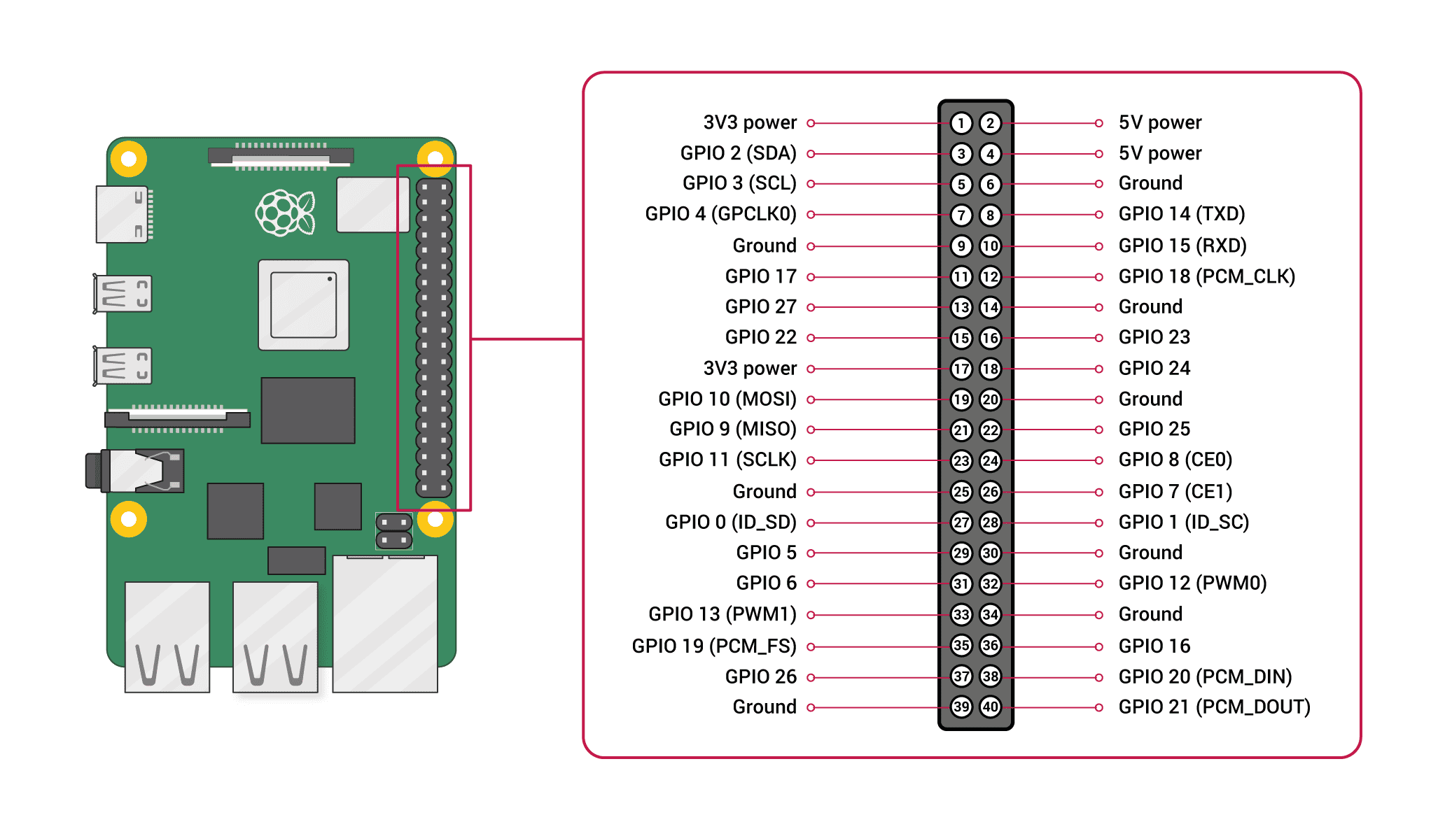
The pins 12/13 and 18/19 generate the PWM signal by hardwarewhile all other pins generate the PWM signal by software.

I recommend that you use one of the pins 12/13 and 18/19, unless you have a good reason not to, such as the following:
The PWM hardware and the headphone jack use the same circuitry as the Raspberry Pi, so the you will not be able to use them at the same time. In other words, if you use the headphone jack on the Raspberry Pi 4 you will have to use PWM in software, with all its limitations.
IMPORTANT: If you do not use pin 18, remember to update the code with the pin you have decided to use.. These examples are set up to use GPIO 18 (pin 12 on the Raspberry Pi 4 expansion port).
PWM signal calibration for your fan
As we saw in detail in the article "Controlling the speed of a fan with PWM"As we mentioned earlier in this article, each fan responds differently to PWM signals.
Each fan has a minimum duty cycle for the fan to start spinning from standstill. On some fans it may be 30% and on others 90% so you need to test it yourself with your fan.
Each fan also has a minimum Duty Cycle so that it does not stop when it is already in motion. You will not be able to lower the Duty Cycle to, say, 5%, expecting the fan to run very slowly. With so little power it will stop long before it gets down to that 5%.
To give you an idea, the fan I'm testing right now stops when the duty cycle drops to about 60%.
You have to keep in mind that both Work Cycles do not have to be the same (and they won't be).
The fan needs more energy (higher duty cycle) to overcome the resistance to start up and will need less energy to keep moving once it is already moving.
All of the above means that you will need to calibrate your specific fan to find these two Duty Cycle values.
You can easily calibrate your fan using the programme pwm_generator.py I have left you before (you can click here to go to it).
You will have to run the programme several times with the fan stopped, by going to each time the Duty Cycle, until the fan starts up. Once you have found that "Minimum duty cycle from standstill"You can use that value, increasing it by a percentage as a safety margin (you can try a 10%).
Then, with the fan running, you will have to run the programme several times, downloading each time the Duty Cycle, until the fan stops. Once you have found that "Minimum duty cycle from in motion"You can use that value, increasing it by a percentage as a safety margin (you can try a 10%).
What if my Raspberry Pi is not the 4, what about other models?

The Raspberry Pi 5 is too new and I haven't used it yet, so I won't be able to tell you much about it, but I have had all the models before 4 and I can tell you about them.
I can tell you that, on the previous Raspberry Pi models, 1, 2, 3 and their variations, the power consumption is much lower than on the Raspberry Pi 4 and I have never needed to use a fan and its temperature has always been kept within very reasonable limits.
However, if you want or need to add the fan to one of these models, it won't be difficult.
I have tested it (and have it running) on the Raspberry Pi 3 and Raspberry Pi 4, so it is well tested on these models.
If you want to test it on another version, the software will probably work as is, or with minimal changes.
All the research and development has been done with a Raspberry Pi 3, only when it was finished I have installed it on the Raspberry Pi 4. The reason is simply that the only Raspberry Pi 4 that I have was occupied for things of home automation, and I could not be removing it.
If you try it with other versions, especially if it is with the Raspberry Pi 5I ask you to leave a message in the comments and then I can update the article with that information.
Raspberry Pi 4
The software is tested on the Raspberry Pi 4 and works flawlessly.
By the way, on the Raspberry Pi 4 I have mounted a special version of the Mini HAT PWM with SMD components and some longer pins so it can be glued to the outside of the box. In my opinion, it has turned out very well.


Raspberry Pi 3
It is the model on which I have done the research and development so it is tested and should work without a problem.
Raspberry Pi 2
When I can I will try it in this version, although it is not very useful because it doesn't heat up and doesn't need a fan. I don't foresee any problems.
Don't confuse hardware and software on your Raspberry Pi
What we have just seen is with respect to the hardware of the Raspberry Pi, but also the software can be different.
The specific version of the operating system I had installed on the Raspberry Pi 3 was: "Raspbian GNU/Linux 11 (bullseye) armv71 (32bit) with 32 bit user space.
The operating system that I had installed on the Raspberry Pi 4 was: "Raspbian GNU/Linux 11 (bullseye) aarch64 (64bit) with 32 bit user space.
If you have followed the tutorial and found something different or not working, it wouldn't hurt to check your version.
To see the version of the operating system installed on your Raspberry Pi, you can use the following command:
cat /etc/os-release
This command will show you the name and version of the operating system running on your device.
If you want to know whether the operating system is 32-bit or 64-bit, you can use the following command:
uname -m
This command will show you the processor architecture of your Raspberry Pi. If the output is armv7lIf the output is aarch64, then you are using a 32-bit operating system. If the output is aarch64, then you are using a 64-bit operating system 12.
To see if the user space of your Raspberry Pi is 32-bit or 64-bit, you can use the following command:
getconf LONG_BIT
This command will show you the processor architecture of your Raspberry Pi. If the output is 32If the output is 32-bit, then you are using 32-bit user space, if the output is 64, then you are using 64-bit user space.
What next?
In this article we have seen what we have to do to control the Raspberry Pi's fan speed depending on the temperature of your CPU.
If you have not done so, I suggest you read the following articles, which provide more information on each of the aspects we have summarised here:
How are you dear, thank you very much for sharing your knowledge.
I want to ask for your help as I have built a nas with several hard drives which eventually get very hot, using your code I can fan based on the temperature of the cpu, but it is the case that the cpu does not get very hot but the disks if, it would be possible to give me a help to add the temperatures of the disks and drive the fan either by the cpu or the disks ?
(I clarify that it is the first time that I use a phyton code)
Thank you very much.
greetings
Hi, thank you very much for the work you have done with this tutorial, I have followed it step by step and now I have my Raspberry Pi working with a fan (with PWM incorporated).
If you allow me a suggestion, would it be possible that every time the fan starts or stops it sends a message via Telegram? I have the bot working with other notifications in the raspi and it works super well. I don't control well the Python programming to do it, but I'm sure it's not complicated, in the script "temperature_pwm_controller.py" implement two "IF", one so that when the minimum cycle is activated send the pulse to the fan to start it and then send another message when the pulse reaches 0% (fan stopped).
I use this snippet for Telegram:
Telegram configuration in a JSON, named: "keys.json".
{ "token": "XXXXXXXXXXXXXXXX:XXXXXXXXXXXXXXXXXXXXXXXXXXXXXXXXXXXXXXXXXXXXXXXXXXXXXXXXXX", "channel_id":"-4579485474"}
And the snippet:
—————————————-
#!/usr/bin/env python3
import subprocess
Import
import json
import requests
def cpu_temp():
thermal_zone = subprocess.Popen(['cat', '/sys/class/thermal/thermal_zone0/temp'], stdout=subprocess.PIPE)
out, err = thermal_zone.communicate()
cpu_temp = int(out.decode())/1000
return cpu_temp
def send_warning(message):
dir = os.path.dirname(os.path.abspath(__file__))
filename = os.path.join(dir,'keys.json')
f = open(filename, 'r')
content = f.read()
f.close()
data = json.loads(content)
url = 'https://api.telegram.org/bot{0}/sendMessage'.format(data['token'])
data = {'chat_id': data['channel_id'], 'text': message}, 'text': message}, 'channel_id': data['channel_id'].
r = requests.post(url, data)
def check_temp():
cpu = cpu_temp()
if (float(cpu) > 45):
send_warning("CPU: "+str(cpu)+"º -> has exceeded 45º threshold")
elif float(cpu) has dropped below the 40° threshold")
check_temp()
print ("CPU: "+str(cpu_temp())+"º")
—————————————-
Thanks again!
Hello Diego.
I'll write it down in case I can take a look at it in the future, but bear in mind that the fan stops and starts many times. I don't find it very practical to send a message every time.
I noticed that the "PWM driver with MOSFET transistor" link leads to the same page as the "PWM driver with BJT transistor" link. Is that correct? Is there a MOSFET build page?