How to control a FPV VTX with Arduino
Some time ago I got it into my head that controlling a 1.2 Ghz video transmitter with an Arduino.
Concretely, what I wanted to achieve was to make a antenna analyserI have yet to describe in the Blog how I did it and publish the code) that I was able to make a frequency sweepfor example from 1.1 Ghz to 1.4 Ghz, with steps every few Mhz, measuring the SWR at each of those steps in order to capture all the data in Excel and make a antenna resonance graph in that frequency range.
I searched a lot on the internet and found very little information, so I decided to start, almost, from scratch and do all the analysis of the protocol that the VTX microprocessor uses to communicate with its PLL IC (an MB15E07L, manufactured by Fujitsu, which is the integrated circuit that creates the broadcast frequency), to know how to control it, and write the Arduino code.
A little reverse engineering never hurt anyone.
Fortunately user Changosurf had already described the PLL protocol, although it didn't work for me as it was and I had to do more research (the 18-bit latch register data didn't work with my VTX, or any of the others I tried).
I also found some code that I used as a base, but, sorry, as it's been several years since I did this project, I can't find the original author to give credit to.
The whole process was done using a 800mw VTX Partom, of the most used in aeromodelling, but the good thing is that almost all the video transmitters that have that physical aspect, like the VTX FOX (and many others), use this same PLL and protocol. In fact, I have tried with other transmitters with different power ratings and other physical aspects and all of them have worked correctly.
What is the use of Arduino control?
The uses are many, and only the imagination is the limit.
In addition to the example mentioned above, which allows us to vary the transmission frequency automatically in order to analyse antennas, we could use it to:
- Change the video channel of our aircraft or drone remotely Do we have interference on the frequency we are using and our model aircraft is far away? Then we change the frequency remotely (we can even change the frequency to save our device or avoid certain loss).
- Use non-standard frequencies: Transmitters usually have between one and eight channels that we can select, this means that everyone is on one of these channels, if we can choose a frequency that does not match any of these channels we can to use that frequency for ourselves alone, exclusively, without interference.
FPV video transmitter architecture
The architecture of a VTX used in FPV is quite simple.
It basically consists of four basic blocks:
- Control circuit: the user selects a broadcast channel via switches or buttons and a microcontroller checks which frequency that channel corresponds to and encodes it so that the PLL can understand it.
- Frequency generator circuit or PLL (Phase-locked Loop): This integrated circuit receives data from the microcontroller indicating the frequency to be generated.
- Radio Frequency (RF) circuit: This block receives the frequency generated by the PLL (which does not have to be the actual broadcast frequency) and using that frequency as a basis will generate the final frequency, the subcarriers, and modulate it with the audio and video.
- Power amplifier: All of the above is done at extremely low powers, it is this final circuit that takes that signal and multiplies it by thousands or millions of times and sends that high power signal to the antenna for broadcasting.
What we are going to do here is to replace the "Control Circuit" with our own so that we can control the PLL as we wish.
PLL protocol analysis

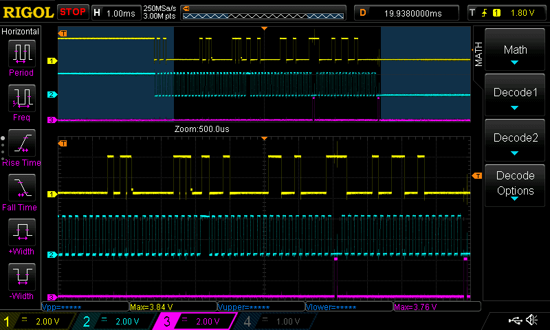
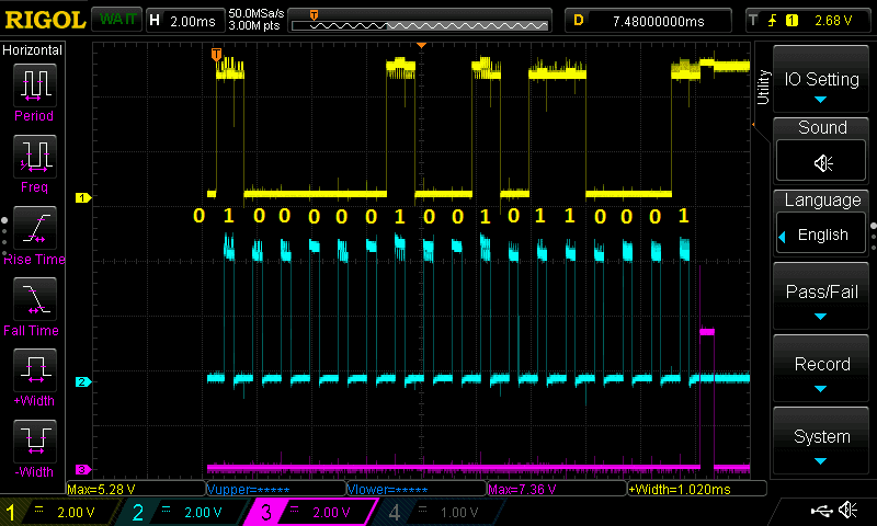
The first thing I did was, before making any modifications to the transmitter hardware, analyse the data on the PLL communication lineswith the help of my oscilloscope RIGOL DS1054Z
I then switched channels manually and, using the oscilloscope (temporarily connected to the VTX with some wires), captured the data that the PIC microcontroller was sending to the VTX.
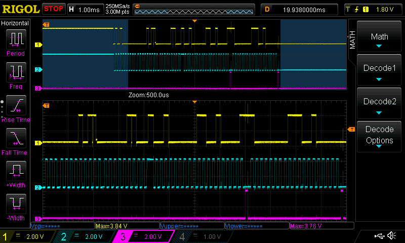
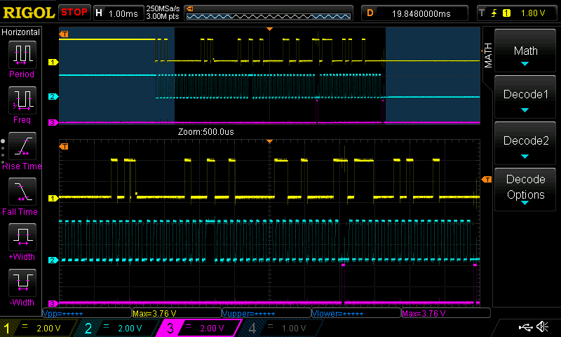
Below, you can see the screenshots I took when switching to the different channels:


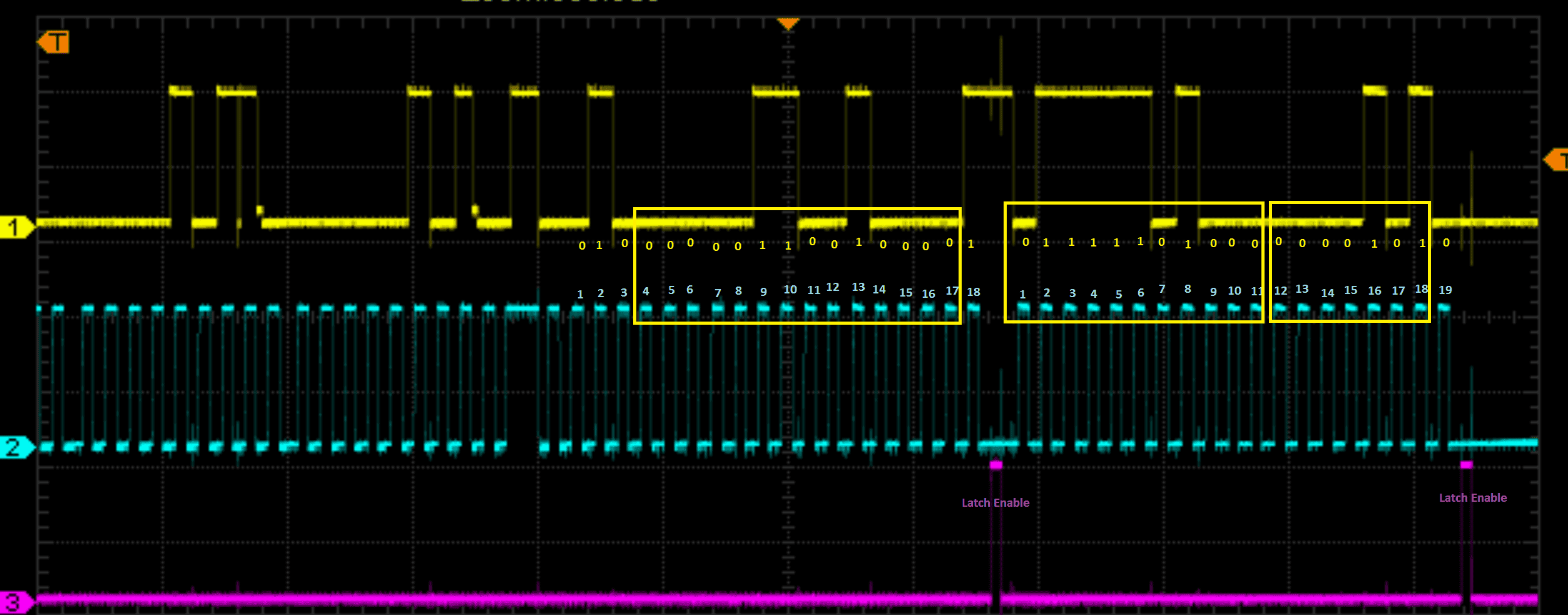
Finally, I used the capture of channel 11 to check whether it was in 18-bit or 19-bit mode:
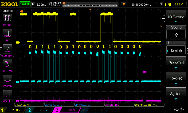
In this last image you can see in detail the analysis of the protocol, as I documented it on the capture with numbered bits to make it easier to visualise:
Arduino sketch code
Here you have the complete code to control the VTX with Arduino.
I recommend, if you are going to use it, that you take it from the eMariete's Github pagewhere you can find the latest version and other interesting information.
To flash the Arduino you can use the regular Arduino IDE. Please note that this code was developed with a 2017 version of the Arduino IDE so there may be incompatibilities with the latest versions.
The code is not a marvel of programming, it's a "quick and dirty" thing to check that it worked and I uploaded it to Github "as it is". I tested it on a 3.3V 8Mhz Arduino Pro Mini and it worked flawlessly.
/*
 * This sketch controls a Partom or simmilar VTX transmit frequency
 * Copyright (c) 2017 Mariete
 */
/*-----( Declare Constants )-----*/
static const const int FREQ[] = {1010, 1040, 1060, 1080, 1100, 1120, 1140, 1160, 1180, 1200, 1240, 1258, 1280, 1320, 1360};
static unsigned long COUNTER18BIT_OLD[] = {
  0b010000010010110001,
  0b010000010010110001,
  0b010000010010110001,
  0b010000010010110001,
  0b010000010010110001,
  0b010000010010110001,
  0b010000010010110001,
  0b010000010010110001,
  0b010000010010110001,
  0b010000010010110001,
  0b010000010010110001,
  0b010000010010110001, /* 12 */
  0b010000010010110001,
  0b010000010010110001, /* 14 */
  0b010000010010110001};
static unsigned long COUNTER18BIT[] = { // Original PLL data for 1280Mhz
  0b010000001100100001,
  0b010000001100100001,
  0b010000001100100001,
  0b010000001100100001,
  0b010000001100100001,
  0b010000001100100001,
  0b010000001100100001,
  0b010000001100100001,
  0b010000001100100001,
  0b010000001100100001,
  0b010000001100100001,
  0b010000001100100001, /* 12 */
  0b010000001100100001,
  0b010000001100100001, /* 14 */
  0b010000001100100001};
static unsigned long COUNTER19BIT[] = {
  0b0110001010100001000,
  0b0110010110001000000,
  0b0110011110000010000,
  0b0110100101101100000,
  0b0110101101100110000,
  0b0110110101100000000,
  0b0110111101001010000,
  0b0111000101000100000,
  0b0111001100101110000,
  0b0111010100101000000,
  0b0111100100001100000,
  0b0111101011001101000, /* 12 */
  0b0111110100000001010,
  0b1000000011100100000, /* 14 */
  0b1000010011001000000};
#define VTXDataPin 7
#define VTXClockPin 8
#define VTXLatchEnablePin 9
#define VTXChannelChangePin 3
/*-----( Declare Variables )-----*/
byte VTXChannelOld = 0;
byte VTXChannel = 13;
void setup()
{
  Serial.begin(9600);
  pinMode(LED_BUILTIN, OUTPUT);
  pinMode(VTXDataPin, OUTPUT);
  pinMode(VTXClockPin, OUTPUT);
  pinMode(VTXLatchEnablePin, OUTPUT);
  pinMode(VTXChannelChangePin, INPUT_PULLUP);
  digitalWrite(VTXChannelChangePin, HIGH);
  digitalWrite(VTXDataPin, LOW);
  digitalWrite(VTXClockPin, LOW);
  digitalWrite(VTXLatchEnablePin, LOW);
}
void loop()
{
  if (!digitalRead(VTXChannelChangePin))
  {
    while (!digitalRead(VTXChannelChangePin)) {
      //
    }
    VTXChannel++;
    Serial.println("Button pressed...");
  }
  if (VTXChannel != VTXChannelOld)
  {
    Serial.println("Changing channel...");
    ChangeChannel();
  }
//  delay(9500);
// digitalWrite(LED_BUILTIN, HIGH);
//  delay(500);
// digitalWrite(LED_BUILTIN, LOW);
// VTXChannel = 13;
// ChangeChannel(VTXChannel);
//  delay(9500);
// digitalWrite(LED_BUILTIN, HIGH);
//  delay(500);
// digitalWrite(LED_BUILTIN, LOW);
// VTXChannel = 11;
// ChangeChannel(VTXChannel);
}
void bitBang(unsigned long pattern, byte numBits) // This function is what bitbangs the data
{
// digitalWriteFast(VTXDataPin, LOW);
// digitalWriteFast(VTXClockPin, LOW);
//  delay(1);
  for(int i=numBits-1; i>-1; i--)
  {
    digitalWriteFast(VTXDataPin, bitRead(pattern, i));
    delayMicroseconds(300);
    digitalWriteFast(VTXClockPin, HIGH);
    delayMicroseconds(350);
    digitalWriteFast(VTXClockPin, LOW);
    Serial.print(bitRead(pattern, i));
    delayMicroseconds(50);
  }
  digitalWriteFast(VTXLatchEnablePin, HIGH);
  delayMicroseconds(500);
  digitalWriteFast(VTXLatchEnablePin, LOW);
  Serial.println("");
  digitalWrite(VTXDataPin, LOW);
}
void ChangeChannel()
{
  Serial.print("VTXChannel: ");
  Serial.println(VTXChannel);
  Serial.print("VTXChannelOld:");
  Serial.println(VTXChannelOld);
  if (VTXChannel < 1) {
    VTXChannel = 15;
  }
  if (VTXChannel > 15) {
    VTXChannel = 1;
  }
  switch (VTXChannel) {
    case 1:
    case 2:
    case 3:
    case 4:
    case 5:
    case 6:
    case 7:
    case 8:
    case 9:
    case 10:
    case 11:
    case 12:
    case 13:
    case 14:
    case 15:
      Serial.print("Change to channel: ");
      Serial.println(VTXChannel);
      bitBang(COUNTER18BIT[VTXChannel-1], 18);
      bitBang(COUNTER19BIT[VTXChannel-1], 19);
      VTXChannelOld = VTXChannel;
      break;
  }
}
void digitalWriteFast(uint8_t pin, uint8_t x) {
  if (pin / 8) { // pin >= 8
    PORTB ^= (-x ^ PORTB) & (1 << (pin % 8));
  }
  else {
    PORTD ^= (-x ^ PORTD) & (1 << (pin % 8));
  }
}
=======
/*
 * This sketch controls a Partom or simmilar VTX transmit frequency
 * Copyright (c) 2017 Mario Elkati (Mariete)
 * [email protected]
 */
/*-----( Declare Constants )-----*/
static const const int FREQ[] = {1010, 1040, 1060, 1080, 1100, 1120, 1140, 1160, 1180, 1200, 1240, 1258, 1280, 1320, 1360};
static unsigned long COUNTER18BIT_OLD[] = {
  0b010000010010110001,
  0b010000010010110001,
  0b010000010010110001,
  0b010000010010110001,
  0b010000010010110001,
  0b010000010010110001,
  0b010000010010110001,
  0b010000010010110001,
  0b010000010010110001,
  0b010000010010110001,
  0b010000010010110001,
  0b010000010010110001, /* 12 */
  0b010000010010110001,
  0b010000010010110001, /* 14 */
  0b010000010010110001};
static unsigned long COUNTER18BIT[] = { // Original PLL data for 1280Mhz
  0b010000001100100001,
  0b010000001100100001,
  0b010000001100100001,
  0b010000001100100001,
  0b010000001100100001,
  0b010000001100100001,
  0b010000001100100001,
  0b010000001100100001,
  0b010000001100100001,
  0b010000001100100001,
  0b010000001100100001,
  0b010000001100100001, /* 12 */
  0b010000001100100001,
  0b010000001100100001, /* 14 */
  0b010000001100100001};
static unsigned long COUNTER19BIT[] = {
  0b0110001010100001000,
  0b0110010110001000000,
  0b0110011110000010000,
  0b0110100101101100000,
  0b0110101101100110000,
  0b0110110101100000000,
  0b0110111101001010000,
  0b0111000101000100000,
  0b0111001100101110000,
  0b0111010100101000000,
  0b0111100100001100000,
  0b0111101011001101000, /* 12 */
  0b0111110100000001010,
  0b1000000011100100000, /* 14 */
  0b1000010011001000000};
#define VTXDataPin 7
#define VTXClockPin 8
#define VTXLatchEnablePin 9
#define VTXChannelChangePin 3
/*-----( Declare Variables )-----*/
byte VTXChannelOld = 0;
byte VTXChannel = 13;
void setup()
{
  Serial.begin(9600);
  pinMode(LED_BUILTIN, OUTPUT);
  pinMode(VTXDataPin, OUTPUT);
  pinMode(VTXClockPin, OUTPUT);
  pinMode(VTXLatchEnablePin, OUTPUT);
  pinMode(VTXChannelChangePin, INPUT_PULLUP);
  digitalWrite(VTXChannelChangePin, HIGH);
  digitalWrite(VTXDataPin, LOW);
  digitalWrite(VTXClockPin, LOW);
  digitalWrite(VTXLatchEnablePin, LOW);
}
void loop()
{
  if (!digitalRead(VTXChannelChangePin))
  {
    while (!digitalRead(VTXChannelChangePin)) {
      //
    }
    VTXChannel++;
    Serial.println("Button pressed...");
  }
  if (VTXChannel != VTXChannelOld)
  {
    Serial.println("Changing channel...");
    ChangeChannel();
  }
//  delay(9500);
// digitalWrite(LED_BUILTIN, HIGH);
//  delay(500);
// digitalWrite(LED_BUILTIN, LOW);
// VTXChannel = 13;
// ChangeChannel(VTXChannel);
//  delay(9500);
// digitalWrite(LED_BUILTIN, HIGH);
//  delay(500);
// digitalWrite(LED_BUILTIN, LOW);
// VTXChannel = 11;
// ChangeChannel(VTXChannel);
}
void bitBang(unsigned long pattern, byte numBits) // This function is what bitbangs the data
{
// digitalWriteFast(VTXDataPin, LOW);
// digitalWriteFast(VTXClockPin, LOW);
//  delay(1);
  for(int i=numBits-1; i>-1; i--)
  {
    digitalWriteFast(VTXDataPin, bitRead(pattern, i));
    delayMicroseconds(300);
    digitalWriteFast(VTXClockPin, HIGH);
    delayMicroseconds(350);
    digitalWriteFast(VTXClockPin, LOW);
    Serial.print(bitRead(pattern, i));
    delayMicroseconds(50);
  }
  digitalWriteFast(VTXLatchEnablePin, HIGH);
  delayMicroseconds(500);
  digitalWriteFast(VTXLatchEnablePin, LOW);
  Serial.println("");
  digitalWrite(VTXDataPin, LOW);
}
void ChangeChannel()
{
  Serial.print("VTXChannel: ");
  Serial.println(VTXChannel);
  Serial.print("VTXChannelOld:");
  Serial.println(VTXChannelOld);
  if (VTXChannel < 1) {
    VTXChannel = 15;
  }
  if (VTXChannel > 15) {
    VTXChannel = 1;
  }
  switch (VTXChannel) {
    case 1:
    case 2:
    case 3:
    case 4:
    case 5:
    case 6:
    case 7:
    case 8:
    case 9:
    case 10:
    case 11:
    case 12:
    case 13:
    case 14:
    case 15:
      Serial.print("Change to channel: ");
      Serial.println(VTXChannel);
      bitBang(COUNTER18BIT[VTXChannel-1], 18);
      bitBang(COUNTER19BIT[VTXChannel-1], 19);
      VTXChannelOld = VTXChannel;
      break;
  }
}
void digitalWriteFast(uint8_t pin, uint8_t x) {
  if (pin / 8) { // pin >= 8
    PORTB ^= (-x ^ PORTB) & (1 << (pin % 8));
  }
  else {
    PORTD ^= (-x ^ PORTD) & (1 << (pin % 8));
  }
}
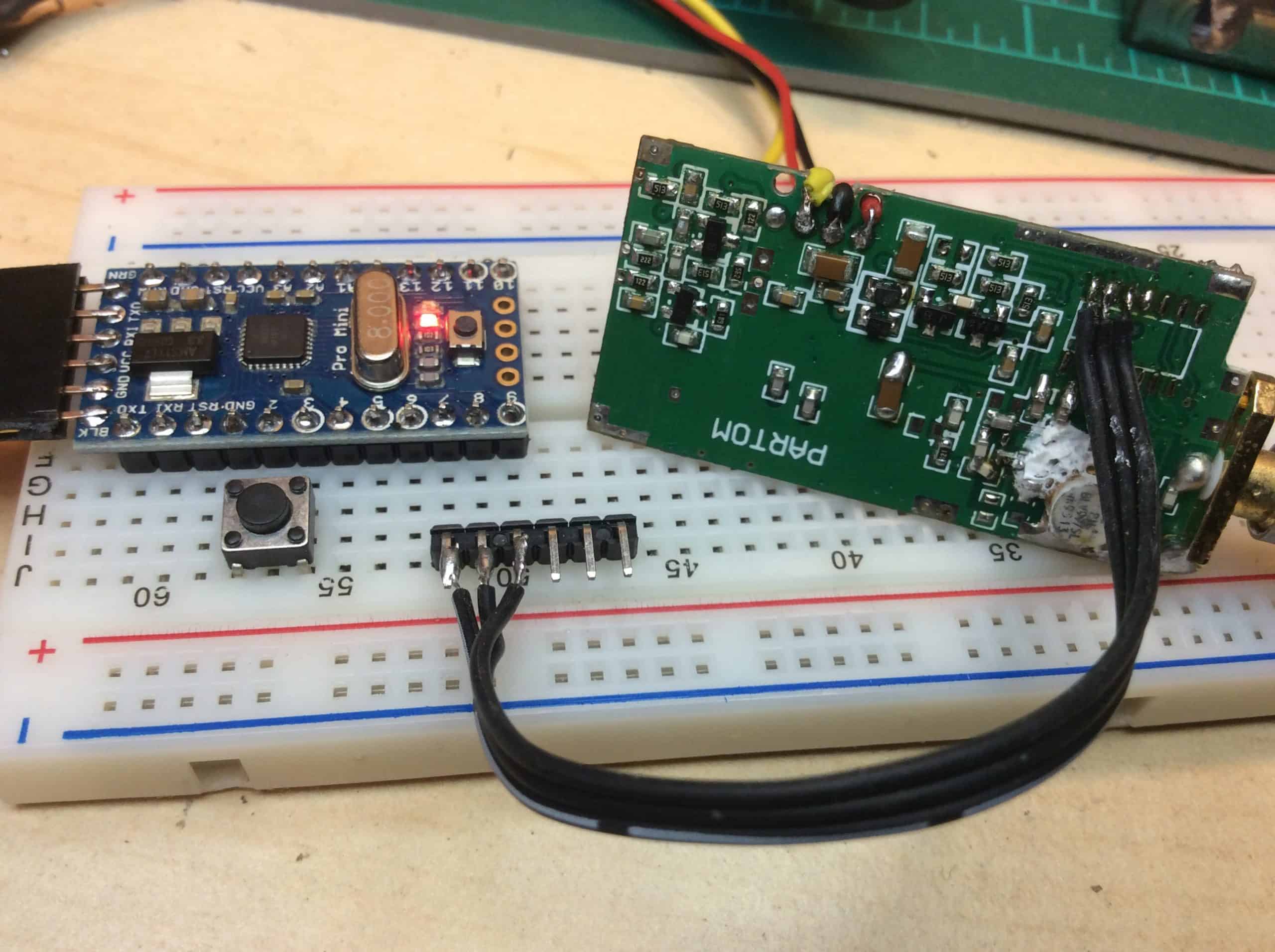
Modification of the VTX and connection to the Arduino
The amendment consists of replace the PIC microcontroller of the transmitter with our Arduinoprogrammed with the code from the previous point.
To do this we will have to carefully unsolder the PIC (14-pin integrated chip) from the board and solder three cables (for DATA, CLOCK and LATCH ENABLE lines) You will also need to connect the ground between them (use a common negative wire, for example).
I think you can see it quite well in the following pictures.

Antenna analyser and SWR tester with Arduino
On the basis of this development, I realised the first interesting project: a stationary meter and antenna analyser. This project allows us to characterise the antenna by means of a frequency sweep, making graphs of the resonance frequency of the antenna, to find the frequency at which it works best or to adjust it so that it gives its maximum performance on the channel we are interested in.
I have yet to properly document and publish this project. If you are interested subscribe to the newsletter of eMariete so you don't miss it and find out as soon as possible.