We are going to add to the electronic load with MOSFET, which we built in a previous article, a basic control by means of an ESP32 microcontroller.
This way we will be able to go to the next level and we can think about doing lots of things and more advanced projects with the ESP32.
As you can imagine, and if you can't imagine it, I'm here to tell you, this article is written using the ESP32, but nothing prevents you from using an ESP8266, an Arduino or another microcontroller, such as the nRF52840 or nRF69936 from Nordic Semiconductor.
THIS IS JUST THE FIRST STEP! In the next article you will see how, based on what we will see here, we are going to build an instrument that will allow us to do a lot of testing, measuring and characterisation.
You will be able, almost automatically, to know the characteristics of a solar panel, a battery or a power supply. All from a web browser, with graphs and automations.
If you haven't already done so, I recommend that you first read the article on basic MOSFET electronic charging, because what we will see here is based on it:
Contents
- 1 How to prepare the load for ESP32 control?
- 2 Modification of the electronic load to be controlled by external voltage
- 3 How do we generate the voltage with the ESP32?
- 4 MOSFET cooling
- 5 Testing using the ESP32 DAC
- 6 Tests using PWM generated by the ESP32
- 7 Testing using the MCP4725 DAC
- 8 What next, the next level! 🚀
How to prepare the load for ESP32 control?
Basically, we have to think about controlling it with an external voltage (which will come from the ESP32) instead of controlling it with the voltage coming out of the voltage divider (the potentiometer).
For that, the first thing we have to do, if we already had it built with the potentiometer mounted, is to slightly modify the electronic load to connect it to the ESP32.
If you remember, that electronic load was controlled by a voltage coming out of a voltage divider made with a simple potentiometer.
I remind you of the scheme to explain it better:

From the intermediate terminal of the potentiometer R2 a voltage was output which we regulated, between 0 and 5V depending on where we adjusted the potentiometer and we put it in the positive comparator (terminal " ").+"(operational amplifier) of the OpAmp (operational amplifier).
What we are going to do is to generate that voltage with an ESP32 and inject it directly into the positive comparator (terminal " ").+") of the OpAmp.
All we need to do is to break the connection between the intermediate terminal of the potentiometer and the OpAmp and connect the voltage output of the ESP32 directly to the " " input.+"OpAmp.
For this we will include a two-pin connector on the electronic load board, for voltage and GND (the two wires that will come from the ESP32).
Modification of the electronic load to be controlled by external voltage
Meet the "method ONE, TWO". Just like in the gym!
Repeat after me:
- Disconnect the potentiometer
- Connect the ESP32
Simple, isn't it?
The only nuance is that instead of connecting the ESP32 directly, I'm going to put a connector to make it easier to test and modify (if you want, you can connect it directly).
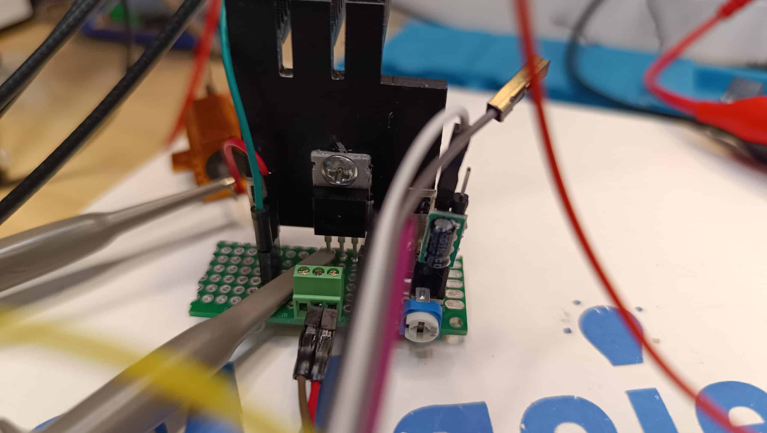
As a picture is worth more than 1000 words and I have already written a lot of words, I leave you two pictures (to be worth more than 2000 words):
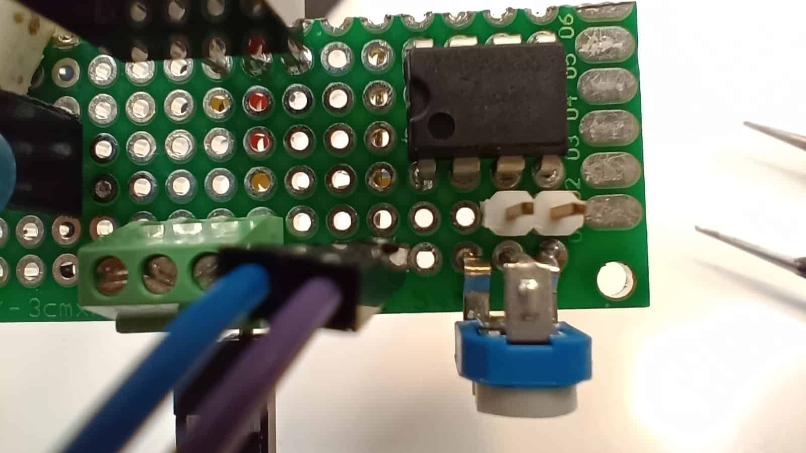
As you can see, I have added a white 2-pin connector.
The pin on the right (the one closest to the edge of the board) will be for connecting to GND of the ESP32.
The left pin (the one in front of the centre potentiometer terminal) will be for injecting the voltage generated by the ESP32.
Just cut or remove the connection from the centre terminal of the potentiometer to pin 2 of the LM358 integrated circuit (marked in red).
The white two-pin connector must be connected to GND (negative) and pin 2 of the LM358 integrated circuit (marked yellow).
That's it! Modified!
A clarification: I have not removed the potentiometer because I think I might want to do some testing with it in the future, so I have simply disconnected its output (the central terminal).
If you don't intend to use it again, you can remove it directly. You may even choose not to put it in at all, especially if you are assembling the load to be controlled by an ESP32 and do not plan to perform further experiments without it.
⚠️ IMPORTANT NOTE ON CABLES AND SAFETY
When making the modification, remember that we are injecting the control voltage, but the load side (MOSFET, R1 and connections to the DUT) is still handling the same high current as before. Make sure that the power supply wires (to the DUT) and the connections of the Source y Drain of the MOSFET remain of appropriate section We don't want to burn any wires, as I did!
How do we generate the voltage with the ESP32?
We basically have four options to generate the necessary voltage with our ESP32.
- Voltage generation with a DAC (Digital Analogue Converter) internal of the ESP32.
- Voltage generation with a PWM signal.
- Using a DAC (Digital Analogue Converter) external.
- Voltage generation by means of delta-sigma modulation.
In my blog, you will find an article in which I compare the different voltage generation systems. I recommend you take a look at it, as it will be of great help in determining which is the most suitable option for your needs.

In my case I will generate the voltage with an external DAC, the MCP4725.
I recommend that you follow my advice and, unless you are building the load just to do some tests, without further pretensions, use the MCP4725.
By adding an MCP4725, for a couple of euros, you will have an easy way to generate a DC voltage with more than enough accuracy for the application we are going to give you.
MOSFET cooling
Depending on the intensity at which you want to adjust the load and how long you want to keep it running, you will need a larger or smaller heatsink (or even none at all, for small currents for short periods of time).
In order to be able to test more comfortably and with more current, I decided to put a heatsink on the MOSFET.

I have put this medium heatsink because it is the one I had. It is salvaged from an old Corsair GS700 PC power supply so I have no technical data.
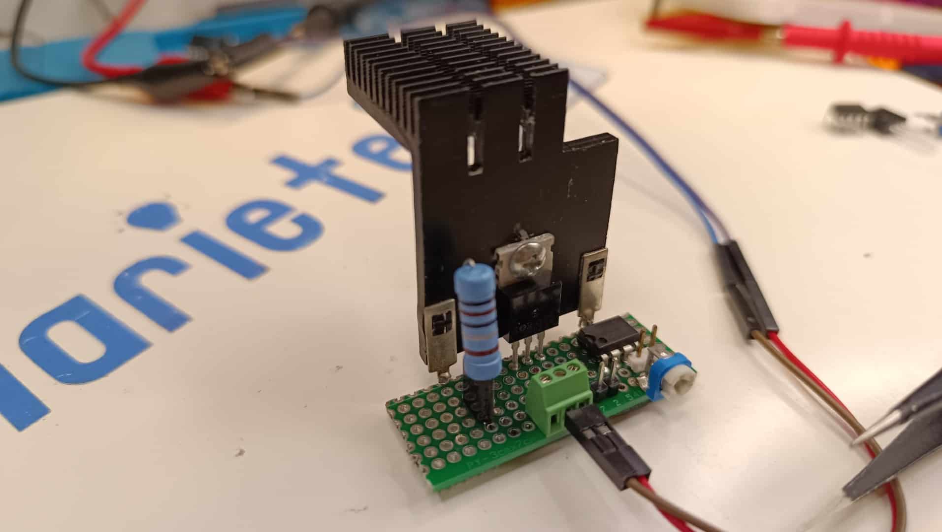
I can tell you one thing: the heatsink must be doing its job very well because during the tests I have burnt some of the wires I am using while the MOSFET was still at a good temperature of about 60ºC at that moment.
Remember I told you to pay attention to the cross-section of the wires? Well I suggest you do what I say and not what I do. 😜
Testing using the ESP32 DAC
To test with the ESP32 DAC I used this small program that allowed me to easily change the output voltage through the serial port (by typing the voltage directly into the terminal).
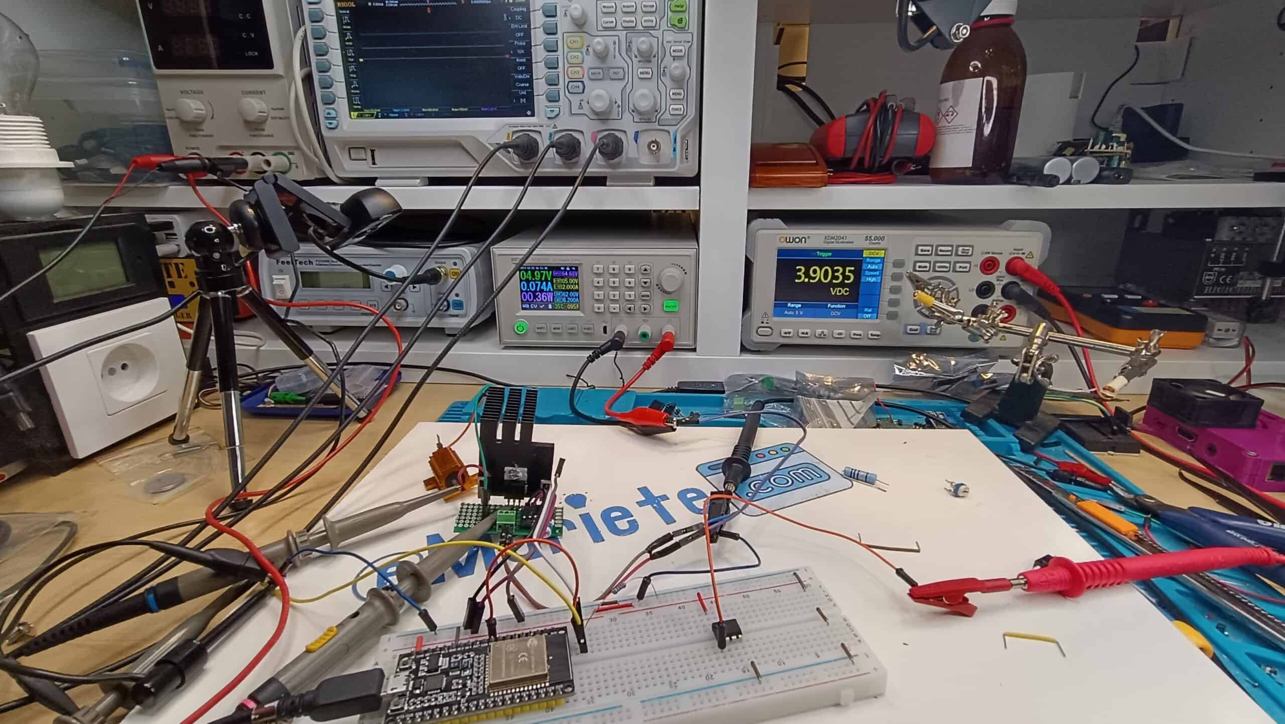
This picture is of the setup I used for these tests:
#include

const int dacPin = 25;
const float referenceVoltage = 3.3;
const float maxVoltage = 3.3;
float targetVoltage = 0;

void setup() {
  Serial.begin(115200);
  pinMode(dacPin, OUTPUT); // Set the pin as OUTPUT
  digitalWrite(dacPin, LOW); // Disable the pullup resistor
  dacWrite(dacPin, 0);
}

void loop() {
  // Read targetVoltage value from the serial port when Enter is pressed
  if (Serial.available() > 0) {
    String input = Serial.readStringUntil('\n'); // Read input until Enter is pressed
    if (input.length() > 0) {
      targetVoltage = input.toFloat();

      // Constrain the maximum value of targetVoltage to the reference
      targetVoltage = constrain(targetVoltage, 0, maxVoltage);

      Serial.print("New targetVoltage: ");
      Serial.println(targetVoltage);
    }
  }

  int dacWriteValue = (targetVoltage / referenceVoltage) * 255;
  Serial.print("dacWriteValue: ");
  Serial.println(dacWriteValue);

  dacWriteValue = constrain(dacWriteValue, 0, 255);
  dacWrite(dacPin, dacWriteValue);
  delay(1000);
}
Although I won't be able to use this solution for this project (because of the expected problem, the DAC offset, which prevents it from going down to 0V), the experiment has worked very well. Maybe it will be interesting for other projects where I don't need to go down to 0V.
Otherwise, I typed in the voltage I wanted on the PC keyboard, pressed [Enter] and at the output it had the requested voltage (plus offset and linearity errors of the DAC).
With that offset at the output of the DAC, the minimum current at which the electronic load dropped was 0.74mA, which is very high for my needs.
Clearly I could lower it by using a higher R1 resistor (I was using the 1Ω resistor) or by modifying the supply voltage of the electronic load (I was supplying it at 5V).
Tests using PWM generated by the ESP32
I have configured pin 27 as a 1Khz PWM output with 10-bit resolution (giving 1024 "steps").
The code used for the tests was as follows:
#include

// Define the PWM channel to use
int pwmChannel = 0;

// Define the pin the PWM is connected to
const int pwmPin = 27;

// Initializes the duty cycle of the PWM to 0%
int dutyCycle = 0;

// Saves the previous duty cycle value
int oldDutyCycle = 0;

// Sets the PWM resolution (10 bits in this case)
const int pwmResolution = 10;

// Sets the frequency of the PWM (1kHz in this case)
const int pwmFrequency = 1000;

void setup()
{
  // Start serial communication at 115200 bauds
  Serial.begin(115200);

  // Configures the PWM with the specified channel, frequency and resolution
  ledcSetup(pwmChannel, pwmFrequency, pwmResolution);

  // Associates the specified pin with the PWM channel
  ledcAttachPin(pwmPin, pwmChannel);

  // Starts the PWM with the initial duty cycle
  ledcWrite(pwmChannel, map(dutyCycle, 0, 1023, 0, 1024));
}

void loop()
{
  // If the duty cycle has changed, display it via the serial port
  if (dutyCycle != oldDutyCycle)
  {
    Serial.print(">DutyCycle:");
    Serial.print(dutyCycle);
    Serial.println(" of 1023");
    oldDutyCycle = dutyCycle;
  }

  // If data is available on the serial port, it reads it.
  if (Serial.available() > 0)
  {
    int key = Serial.read();
    // If the key pressed is the escape key and there are at least two more characters in the buffer
    if (key == 27 && Serial.available() >= 2)
    {
      Serial.read(); // Discard the next character ('[')
      switch (Serial.read()) // Reads next character
      {
      case 'A': // If 'A' (up arrow), increments duty cycle
        oldDutyCycle = dutyCycle;
        dutyCycle = min(1023, dutyCycle + 5);
        break;
      case 'B': // If 'B' (down arrow), decrements duty cycle
        oldDutyCycle = dutyCycle;
        dutyCycle = max(0, dutyCycle - 5);
        break;
      }
    }
  }

  // Update the PWM output with the new duty cycle.
  ledcWrite(pwmChannel, map(dutyCycle, 0, 1023, 0, 1024));

  // Wait 100 milliseconds before the next loop iteration
  delay(100);
}
This code allows, for the convenience of experimentation, to modify the duty cycle of the PWM signal from the serial terminal with the up and down arrows in 5-step increments of the 1024 available.
From the tests I have done, the result has been completely positive, although I think it is better to use the MCP4725 DAC (after all, to use the PWM signal, you have to put a low-pass RC filter, as I will explain below).
Now, to convert the PWM pulse signal into a variable DC voltage, I must add a low-pass filter at the output, built with a 4.7kΩ resistor and a 1uF electrolytic capacitor.
The assembly of the low pass filter is very easy.
Here is the schematic:

And here you can see the effect of this simple filter:

Channel 1 (yellow) corresponds to the PWM signal as generated by the ESP32.
Channel 2 (in blue) is the output of the filter, with that PWM signal applied to the input.
In my case, I have built the filter on a small separate board with two connectors for easy testing and interchangeability:


In this diagram you can see the connections of the small plate with the RC filter:

Here you can see the filter mounted on the PWM input of the electronic load during testing.
Testing using the MCP4725 DAC
I can only say one thing: I had never used it before and I am delighted.
It is super easy to use an MCP4725 to generate voltage and the voltage generated is super stable.
I honestly believe that this is the perfect solution for electronic charging. Unless it is for a one-off proof of concept it is not worth using a PWM signal or the ESP32's internal DAC.
This is a very simple test code that allows us to adjust the output voltage of the MCP4725 from the serial terminal.
#include
#include
#include

#define SDA_PIN 33
#define SCL_PIN 32

Adafruit_MCP4725 dac;

void setup() {
  Serial.begin(115200);
  Wire.begin(SDA_PIN, SCL_PIN);

  dac.begin(0x60); // Default I2C address 0x60, if not working, try 0x62

  // Configure the MCP4725 according to your needs (you can change the reference to 4096 for a 4.096V reference)
  dac.setVoltage(0, false); // Set initial voltage to 0V
}

void loop() {
  // Displays the current voltage value over the serial port
  Serial.print(">Output voltage: "); Serial.print(dac.readVoltage()); Serial.println(" V");
  Serial.println("");

  // Update the voltage according to the arrow keys
  if (Serial.available() > 0) {
    int key = Serial.read();
    if (key == 27 && Serial.available() >= 2) { // Detect arrow key sequence
      Serial.read(); // Discard '['
      switch (Serial.read()) {
        case 'A': // Arrow up
          dac.setVoltage(dac.readVoltage() + 0.01, false); // Set the voltage up (you can change the value according to your needs)
          break;
        case 'B': // Arrow down
          dac.setVoltage(dac.readVoltage() - 0.01, false); // Set the voltage down (you can change the value according to your needs)
          break;
      }
    }
  }

  delay(100);
}
What next, the next level! 🚀
We have achieved the most important thing: control the electronic load digitally using an ESP32 microcontroller, and we have confirmed that it works with its internal DAC and PWM.
However, in order to convert this base into a laboratory instrument capable of making professional measurementsWe need two things that ESP32 does not give us with sufficient precision:
- Ultra-fine current control: We need more than the 8 or 10 bits of resolution provided by the PWM or the internal DAC.
- High Precision Measurement: We need to read the source current and voltage (DUT) simultaneously and very accurately.
In the next article, we will make the final leap. We'll use the same base you already have, but we'll add to it:
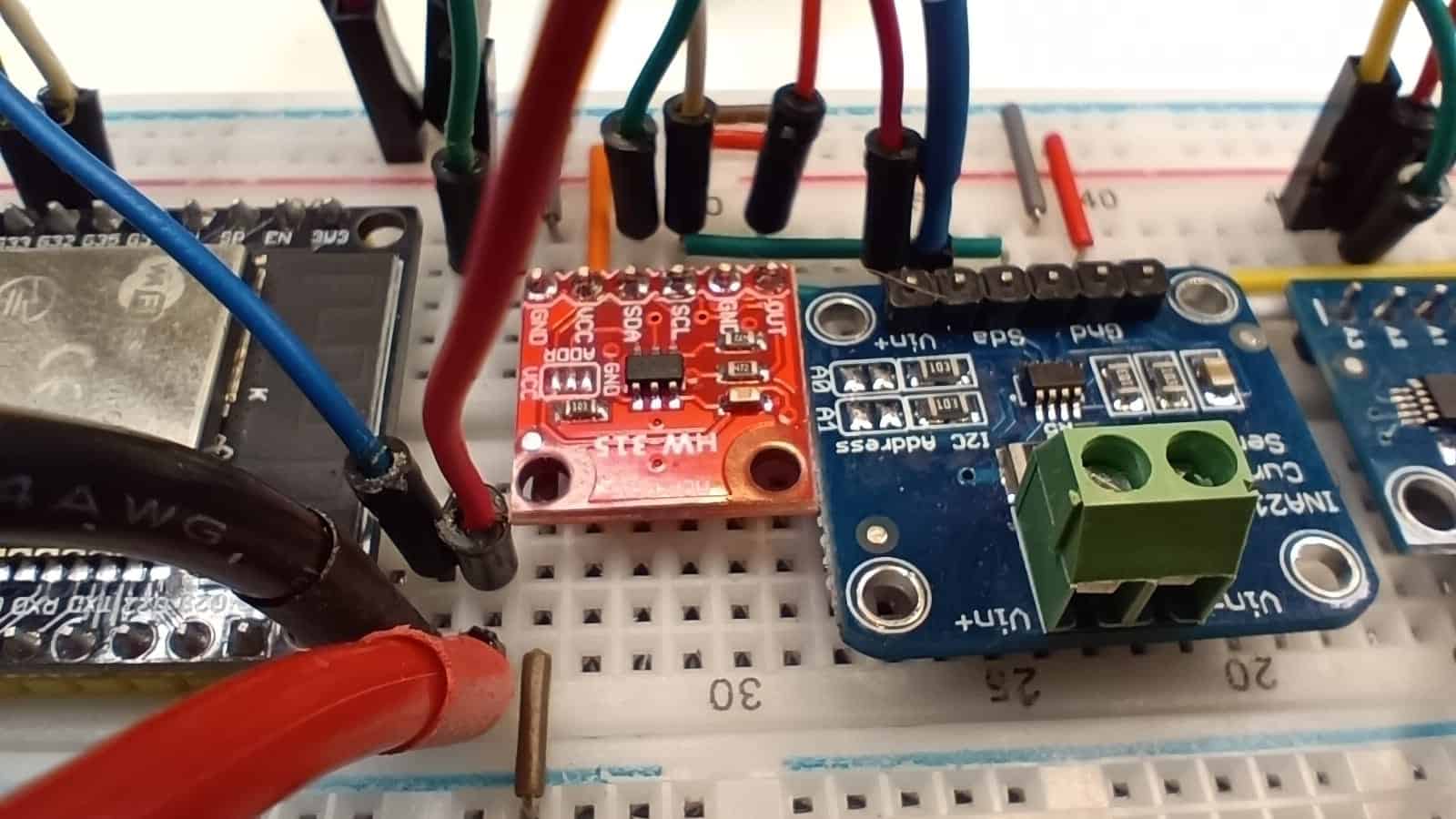
- A External DAC (MCP4725) 12-bit for 4096-step control.
- A power monitor INA3221 three-channel for extremely high accuracy current and voltage readings.
With these two modules, we will build a Load and Source Analyser which will allow you to automatically obtain the V-I curves (Voltage-Current) from any source, solar panel, battery or charger.
Get ready! We will cease to be fans of the DIY to become instrumentation engineers in the next post.
Hola, interesante. Agradezco la aportación que realiza en este sector.
¿Con la misma intención que realiza su carga electrónica con control digital, es posible hacerlo para caracterizar descarga de baterías de alta corriente? ¿Se podría crear a su vez una fuente de potencia programable para también hacer la carga de las baterías?
Greetings
Hola, José. Muchas gracias por tu comentario.
Sí, el mismo principio de la carga electrónica controlada digitalmente puede ampliarse para caracterizar descargas de baterías, incluso a corrientes altas, siempre que el diseño del MOSFET, la disipación y la medición estén dimensionados para ello. Y también es posible crear una fuente de potencia programable para carga, aunque en ese caso la electrónica es distinta y requiere un control más cuidadoso para gestionar perfiles de carga seguros.
¡Gracias por tu interés!