
It’s clear that using a MOSFET as a switch opens up a whole host of possibilities. The sky’s the limit—and so is your imagination.
Imagine having a switch that not only turns things on and off quickly, following instructions from your microcontroller (or another circuit), but also adapts like a chameleon to your needs. Yes, that’s exactly what a MOSFET does. It’s like the all-rounder of electronics.
Using a MOSFET (Metal-Oxide-Semiconductor Field-Effect Transistor) as a switch enables our controller to handle medium- and high-power loads very simply and efficiently.
In this article, I explain how you can use a MOSFET (Metal-Oxide-Semiconductor Field-Effect Transistor) as a switch.
As on other occasions, we’ll look at a bit of theory (I promise it’ll be brief and understandable) and we’ll move on to some practical applications.
This post isn’t intended to be an academic article, as the field of MOSFETs is very complex and wide-ranging, but it does aim to help you overcome your apprehension and gain a better understanding the how, the when and the why.
As always, I’ll try to make sure it’s not just a ‘recipe’ what you need to do to set up a circuit. I'll try to make it I hope this article proves useful to you and that you find it informative easily and without too much hassle.
This article isn't for you, if all you want is a brief guide to building a circuit that allows you to control a load, without knowing what you're doing or how it works. There’s already plenty of information on that subject available online, time and time again.
The MOSFET transistor
A MOSFET is a special type of transistor, which stands for «Metal-Oxide-Semiconductor Field-Effect Transistor», and has certain advantages over traditional transistors (which are BJT transistors).
The vast majority of transistors used today are MOSFETs, due to their significant advantages.
The 10 Main Advantages of MOSFETs in Electronics
MOSFETs are true heroes in the world of electronics. Their versatility and efficiency make them essential components for numerous devices and circuits. Below, we explore the 10 key advantages that make MOSFETs true champions in the realm of electronic components.
1. Impressive Switching Speed:
MOSFETs are lightning fast. Their ability to switch states (from on to off and vice versa) in an extremely short time makes them ideal for applications that require rapid response times.
2. Energy Efficiency:
Want to save energy? MOSFETs are your best bet. Compared to other transistors, MOSFETs have low on-resistance (Rds(on)), which means they lose less energy in the form of heat.
3. Precise Current Control:
As their behaviour is controlled by the gate voltage, MOSFETs allow for precise control of the current flowing through them. This makes it easy to adapt them to the specific requirements of a circuit.
4. Compatibility with analogue and digital signals:
MOSFETs are versatile. They can operate with both analogue and digital signals, making them a flexible choice for a wide range of applications.
5. Low power consumption in standby mode:
When switched off, MOSFETs draw very little current, making them ideal for devices that require low power consumption during periods of inactivity.
6. Compact size and light weight:
In the world of miniaturisation, MOSFETs stand out. Their compact size and light weight make them ideal for applications where space is limited and efficiency is key.
7. Reliability at high frequencies:
MOSFETs are capable of switching at very high frequencies without losing efficiency. This makes them the preferred choice for circuits operating in the radio-frequency range.
8. Low temperature sensitivity:
Unlike some electronic devices, MOSFETs are less sensitive to temperature fluctuations, which helps to ensure greater stability under a variety of environmental conditions.
9. Durability and Extended Service Life:
Thanks to their robust design and the absence of moving parts, MOSFETs tend to have a long service life, making them ideal for applications that require long-term reliability.
10. Ease of integration into circuits:
MOSFETs work well with other electronic components. Their design allows for easy integration into more complex circuits, simplifying the design and manufacturing process.
Types of MOSFETs available
There are thousands of different MOSFETs, each with different characteristics and operating parameters.
Not to mention the MOSFETs that are available inside of integrated circuits. For example, a Core i7 980X processor, with 6 cores and 12 MiB of cache, has a whopping 1.17 billion transistors (of which I assume all, or 99.999%, are MOSFETs).
As you can imagine, selecting a MOSFET to use as a switch for a small or medium-sized load (which is what we’re talking about here) is not the same as using it in a mobile phone to meet its radio frequency transmission requirements in the several GHz range, or using it to build a power supply
Yes, there are thousands of different MOSFETs, and the good thing is that they are all necessary and can be used in one way or another.
We cannot begin to discuss MOSFETs without mentioning the main types that exist and categorising them in some way
MOSFET transistors Channel N and from Channel P
This is the main distinction between MOSFETs. All MOSFETs, regardless of other factors, fall into one of these two categories.
They differ mainly in the polarity of their conduction channel. Here’s an explanation of the basic differences between them:
- Conduit:
- N-channel MOSFET: In this type of MOSFET, the conduction channel is formed by negative charge carriers (electrons) in the semiconductor material. To turn on an N-channel MOSFET, a positive voltage is applied between the gate and the source to create an electric field that allows electrons to flow between the drain and the source.
- P-channel MOSFET: In this type of MOSFET, the conduction channel is formed by positive charge carriers (holes) in the semiconductor material. To turn on the P-channel MOSFET, a negative voltage is applied between the gate and the source to create an electric field that allows holes to flow between the drain and the source.
- Polarity of control voltages:
- N-channel MOSFET: It is activated when a positive voltage is applied between the gate and the source.
- P-channel MOSFET: It is activated by applying a negative voltage between the gate and the source.
- Conductivity and operation:
- In terms of conductivity, N-channel MOSFETs generally have a lower on-resistance than P-channel MOSFETs.
- N-channel MOSFETs tend to be more common in power switching applications, as they generally offer better efficiency and lower on-resistance.
- Applications:
- Both types of MOSFET have specific applications depending on the circuit’s requirements. N-channel MOSFETs are more common due to their superior performance in many applications, but P-channel MOSFETs are also used in specific circuit designs.
In summary, the main difference between an N-channel MOSFET and a P-channel MOSFET lies in the charge carriers (electrons for N-channel, holes for P-channel) that conduct current between the drain and the source when the device is turned on, as well as in the voltage polarities required to turn them on.
Among MOSFETs, both N-channel and P-channel types, there are a type of MOSFET special and which is of particular interest to us: The Logic-level MOSFETs (o Logic-level MOSFET).
More than just a ‘guy’ of a different MOSFET, on Logic-level MOSFETs is a MOSFET ‘normal’ with a set of features or operating parameters that make it ideal for use with microcontrollers, and that that's probably the one you'll want to use as a switch.
I’ll tell you all about the Logic-level MOSFETs When we look at the other types of MOSFETs – and I’ll cover this in a separate section dedicated solely to it, given how important it is to us.
Power MOSFETs
- Features:
- Designed to handle high voltage and current levels.
- Used in power applications, such as power supplies, inverters and motor control systems.
- Variants:
- Enhancement Mode: They require a voltage at the gate to enable operation.
- Depletion mode: They operate automatically and switch off when a voltage is detected at the gate.
Dual-channel MOSFETs
- They contain both an N-channel and a P-channel in the same package.
- They are used in applications where it is necessary to control both positive and negative currents.
Quad-channel MOSFETs
- They include two N-channels and two P-channels in the same package.
- They offer greater versatility in complex applications.
Metal-Oxide-Semiconductor Field-Effect Transistors (SiC MOSFETs)
- They use silicon carbide (SiC) as a semiconductor material.
- Ideal for high-power and high-temperature applications.
Semiconductor-on-Insulator (SOI) Field-Effect Transistors (MOSFETs)
- They use an insulating oxide layer between the substrate and the channel.
- They reduce interference between transistors and improve performance.
These categories provide an overview of the types of MOSFETs available, but within each category there are numerous variants and specific models designed to meet particular requirements in different applications.
The choice of MOSFET type depends on factors such as the specific application, power requirements and environmental conditions.
Symbols and pins of MOSFET transistors
The symbol for the most commonly used MOSFET transistor is as follows (depending on whether it is an N-channel or P-channel device):


Pins:
D = Drain
G = Gate
S = Source
As you can see, a MOSFET generally has three legs, or pins:
- Gate (G): The gate is the input pin of the MOSFET. Applying a voltage between the gate and the source creates an electric field that controls the conduction of the MOSFET. In the case of an N-channel MOSFET, a positive voltage applied to the gate relative to the source allows electrons to flow from the source to the drain, thereby enabling current to flow between the drain and the source.
- Drain (D – Drain): The drain is the output terminal of the MOSFET. Current flows from the source to the drain when the MOSFET is turned on (when there is a sufficient potential difference between the gate and the source). The drain is where the device’s output current is tapped.
- Source (S – Source): The source is the reference pin for current in a MOSFET. Current flows from the source to the drain when the MOSFET is turned on. In an N-channel MOSFET, the source is the terminal where electrons enter the device from the semiconductor substrate.
In summary:
The door controls the current flow between the drain and the source. Applying a voltage to the gate creates an electric field that determines whether the MOSFET is in the on (conducting) or off (blocking) state.
The source is the voltage and current reference for the device, and the drain is where the output current is taken.
The relationship between the voltage applied to the gate and the current flowing between the drain and the source is what makes the MOSFET a voltage-controlled device.
The hidden component in the MOSFET: the capacitor
There is one very important aspect of MOSFETs that we have yet to discuss from a practical point of view:
Inside a MOSFET transistor, there is a capacitor hidden between the gate and the source.

The datasheet itself gives us a clue to this in the symbol it uses for the component.
If you look closely, you’ll see that the MOSFET symbol hides the symbol for three capacitors.
The fact is, there isn’t just one, but three hidden capacitors, although the one we’re concerned with in this case is the one between Gate y Source.
This is very important for one reason, and the following paragraph gets to the heart of the matter:
When we apply voltage to the MOSFET gate to turn the MOSFET on and make it conduct, the internal capacitor is charged. That capacitor does not discharge on its own (it does discharge, but over a relatively long period of time), which means that Until we discharge the capacitor ourselves, the MOSFET will continue to conduct.
The internal resistance of the MOSFET between the gate and the source is so high (in the order of several MΩ) that there is insufficient continuity to discharge the internal capacitor connected between them.
How do I discharge the capacitor between the door and the power supply?
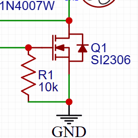
Simple: we just need to add an external discharge resistor. This is the 10 kΩ resistor you can see in the diagram, and its main purpose is to discharge the internal capacitor.
But watch out!
- If we set the resistance too low, we will place a heavy load on the controller's output, increasing intensity and consumption.
- If we set the resistance too high, the capacitor will not discharge quickly enough and the MOSFET will take a long time to switch off between pulses (or may not switch off completely at all).
Physical appearance of a MOSFET
A MOSFET looks very similar to any standard BJT transistor, and depending on its power rating, the packages can be larger or smaller (as with any standard BJT transistor).
At first glance, it looks no different from a BJT transistor, and you have to examine the circuit very carefully to tell whether a transistor is a BJT or a MOSFET just by looking at it.
Of course, there are standard-sized MOSFETs (through-hole o THT), they are available in SMD format, and there are even large, high-power MOSFETs designed to be bolted in place (due to their heavy weight or cooling requirements) and wired in an open configuration.
There is one important point to bear in mind: Logic-level MOSFETs (logic-level MOSFETs) are relatively modern components, and in this world of ever-increasing miniaturisation, it is It is very difficult to find this type of MOSFET in a packaged form through-hole.
Most logic-level MOSFETs are packaged in a surface-mount format (SMD).
The Logic-Level MOSFET: What exactly is it?
When we talk about MOSFETs in general, we are talking about voltage-controlled components who are more or less capable of driving depending on how much voltage we apply between the gate and the source (the voltage between the pins Gate y Source, Vgs).
The relationship between the amount of voltage we apply (Vgs) and how much current the MOSFET can handle is not linear; this is usually shown in MOSFET datasheets in a table featuring a curve that illustrates this relationship within its operating range.
Of course, this is a completely analogue, in which there is a countless possible values.
In a world digital, which is what we’re interested in, something like that isn’t interesting or useful to us. What we want is 0s and 1s. Whether there is a signal or not. Whether the voltage is 0V or, say, 5V.
Furthermore, in many MOSFETs, the voltage that needs to be applied is 10V, 20V or more, just so that let's get started to drive. For full conduction, the voltages can be much higher.
Of course, this isn’t at all suitable for us when working with microcontrollers, which operate at much lower voltages.
A logic-level MOSFET is one that operates at a voltage Vgs suitable for the microcontroller with which we intend to use it, and for which the curve showing the relationship between the applied voltage and the current conduction is as steep as possible
It is as close as possible to ALL-NOTHING, 0-1, YES-NO – as binary as it gets.
Like everything else, logic circuits have evolved over time.
In the 1980s, logic levels were referenced to 0V (for low) and 5V (for high).
Shortly afterwards, the voltage in the high-level logic circuits dropped, almost as a matter of course, to 3.3V
Nowadays, the voltage representing the high logic level continues to fall, and it is now quite common to see 1.65V as the high logic level (or even lower).
This means that the reality that defines what is The voltage of a logic-level MOSFET is changing. Whereas it used to be 5V and, until recently, 3.3V, it is now 1.65V and will continue to fall.
Let me just make a quick point: Although some manufacturers do specify in the datasheet whether a particular MOSFET is of the logic level, but many don’t. In fact, there are many logic level that require a voltage (Vgs) of 4V or more, so from the perspective of a Raspberry Pi or an ESP8266, they would not be a logic-level MOSFET.
The selection of the MOSFET as a switch
It is important to select a MOSFET that can handle the current required by the load it is to control and dissipate the power generated.
Furthermore, the MOSFET driver (the circuit that controls it) must be capable of providing the signal required to control it.
If the MOSFET is controlled by a microprocessor (operating at 3.3V or 5V), it is essential to use a MOSFET with logical level or ‘Logic Level’ MOSFET.
Logic-level MOSFETs or ‘Logic Level‘ are designed to operate on an all-or-nothing basis between the drain and the source with a very low voltage signal (3.3V, 5V or sometimes less) on the door.
How do I choose the right MOSFET?
Selecting the right MOSFET for your application—in this case, using it as a switch—involves taking several factors into account.
If you're new to electronics, it might seem a bit complicated at first glance. If you take a look at the following brick If you make an effort to understand it, you'll see that it's actually quite easy.
The MOSFET does indeed have many important features, but we’re going to limit ourselves to selecting the two or three most important ones.
In any case, if you don’t quite get it at first, carry on reading, because the rest of the article—packed with examples and practical case studies—will help you understand it. When you’ve finished, come back here and you’ll find that you see it in a whole new light, and that everything seems much easier and clearer.
Here are a few steps and points to consider to help you choose the right MOSFET for your load:
- Load current (I_Load): Measure the current that will flow through the load during normal operation.
- Load supply voltage (V_Load): Check the operating voltage of the load you are going to use.
- Power dissipated in the MOSFET (PMOSFET): Calculate the power dissipated in the MOSFET during operation. The power dissipated can be calculated using the formula: PMOSFET = Icargo2 x RDS(on) where RDS(on) is the on-resistance when the MOSFET is turned on.
- Gate current (I_G): Ensure that the control device (e.g. a microcontroller) is capable of supplying the gate current required by the MOSFET to switch between the on and off states. Refer to the MOSFET specifications for the gate current (IG).
- Voltage threshold (Vth): The gate-to-source voltage required for the MOSFET to start conducting a significant current. In other words, 5th is the voltage minimum which must be applied between the gate and the source to turn on the MOSFET and allow current to flow between the drain and the source.
- Gate voltage (VGS): Make sure that the control voltage (VGS) is compatible with the device’s control logic (for example, the voltage levels of a microcontroller). When VGS reaches or exceeds 5th, the MOSFET enters the conduction region.
- Maximum gate voltage (VGS-max): the maximum safe voltage difference that can be applied between the gate and the source of the MOSFET without damaging the device. Exceeding VGS-max may cause permanent damage to the MOSFET.
- Switching frequency: Consider the switching frequency if you need to control the load quickly. Some MOSFETs may not be suitable for very high frequencies.
- MOSFET type (N-channel or P-channel): Make sure you select the correct type of MOSFET for your circuit configuration. For example, if you are using a PWM controller to regulate the speed of a fan, an N-channel MOSFET is usually the standard choice.
- Encapsulation and Thermal Management: Consider the MOSFET’s packaging and its heat dissipation capacity. Heat dissipation is important, especially if you are handling significant currents.
- Conduction resistance (RDS(on)): The on-resistance of the MOSFET (RDS(on)) is critical. A lower resistance results in less power loss and less heat build-up in the MOSFET during switching. Look for a MOSFET with a low on-resistance.
I would like to emphasise that two parameters that are particularly important and which will determine which MOSFET we choose:
RDS(on) y Gate voltage (VGS).
The importance of value RDS(on) of the MOSFET (crucial!)
👉 Please note: This is an exam question. 🤣
The value RDS(on) represents the internal resistance of the MOSFET when you are driving.
This means that if we choose a MOSFET with a RDS(on) of 5Ω would be like having a 5Ω resistor in series with the load when it is switched on, and that is not what we want.
That resistance would cause a drop in voltage (our load would receive less power) and generate heat, resulting in a loss of energy in the form of heat.
That being the case, what we want is a MOSFET with the lowest possible RDS(on) as possible.
The ideal value of RDS(on) would be zero, but, unfortunately, a perfect MOSFET with a RDS(on) of zero does not exist.
Depending on the application, we usually select our MOSFET based on its RDS(on) as low as possible.
The power dissipated by our MOSFET
The power dissipated in a MOSFET (Pd) can be calculated using the basic power formula  .
.
Where:
 is the power dissipated,
 is the current flowing through the MOSFET
 the resistance of the MOSFET when it is in the on-state
It is important to note that resistance represents the resistance when the MOSFET is in the on-state. When the MOSFET is on, there is a voltage drop across this internal resistance, and the power dissipated is proportional to the square of the current flowing through the resistance.
It is advisable to check the MOSFET manufacturer’s specifications to obtain the exact value of as this can vary depending on the model and temperature. Also, bear in mind that the power dissipation will also depend on how long the MOSFET remains in the ON state and on other circuit factors.
In power applications, it is common to use heat sinks to ensure that the MOSFET’s temperature remains within safe limits.
The particular importance of VGS and Vth
The gate voltage (VGS) of the MOSFET transistor we choose is the second factor we need to bear in mind.
As we have said, this value is the voltage that must be applied between the gate and the source. This parameter is crucial because it determines whether the MOSFET is on or off and, therefore, controls the flow of current between the drain and the source.
In an N-channel MOSFET, when a sufficiently high positive voltage (VGS > Vth, where Vth is the gate threshold voltage), an electric field is created that allows electrons to flow from the source to the drain, thereby activating the MOSFET. When VGSIf it is below the threshold, the MOSFET is in the off state and no significant current flows.
In a P-channel MOSFET, the polarity of the voltage is reversed. To turn the MOSFET on, a negative voltage (VGS < – Vth).
The VGS is an important parameter to consider when selecting a MOSFET, as it determines the MOSFET’s compatibility with the control logic used in the circuit. It is essential that the VGS the voltage required to trigger the MOSFET is reliably achieved by the control signal used in the circuit, such as the output of a microcontroller.
In other words, if we are going to control the MOSFET using a microcontroller that supplies 3.3V, VGS must be 3.3V or less to ensure that the MOSFET operates at full capacity.
When checking the MOSFET specifications in its datasheet, you will find values such as Vth (voltage threshold) and VGSmaximum. It is essential that the control signal supplied to the circuit can reach or exceed the threshold to ensure reliable operation of the MOSFET.
Is a diode needed in parallel with the load?
When using an inductive load (such as a motor – and a fan has a motor), it is advisable to include a diode in parallel with the motor to protect the transistor from reverse voltages generated in the windings when the motor is switched off.
This can sometimes be difficult for someone with no background in electronics to understand, but think about the following and you’ll see that it makes perfect sense:
When we turn the motor by hand, without power being supplied to the circuit, generates voltage (it's like a generator). The same thing happens if the motor continues to move after the power is cut off, due to its own momentum (it would be as if we were moving it by hand or using a force external to the motor), will cause tension.
Furthermore, the motor windings themselves store energy (in the form of a magnetic field) which is ‘expelled’ when the power is switched off.
Any coil stores energy in the form of a magnetic field (due to the self-induction effect), which is ‘expelled’ when the power is cut off (it works like a car’s shock absorber).
In the vast majority of cases, a small motor, such as that in a 5V fan, will not generate enough power to damage a MOSFET, but it is a best practice put it on.
In any case, bear in mind that some MOSFETs are more sensitive than others to this reverse voltage and may be damaged.
A purely resistive load, such as an LED or a light bulb, does not exhibit the self-induction effect and you don't need the diode.
What next?
I think we’ve covered the most important aspects of using a MOSFET transistor as a switch.
It remains to be seen whether there will be any case study, Don't you think so?
I suggest you take a look at the following article on using a MOSFET transistor to control a load via a PWM signal.
This is simply a MOSFET that acts as a switch, opening and closing in a specific pattern, in time with a microprocessor, to generate a signal that controls, for example, a fan in this case.
The article is accompanied by a video that isn't finished yet, so I suggest you subscribe to my YouTube channel by clicking the button below, so you'll receive a notification when I publish it and Don't miss it.
That's an excellent explanation – I've understood it all, or nearly all of it. I'll try to keep up with you here, although I sometimes get a bit lost browsing the web.