As part of the series of articles I am writing on fan control with PWM, in this article I explain how a PWM controller or driver works with a BJT transistor (a "normal" bipolar transistor, PNP or NPN, the usual ones).
Of course, everything we will see here is also applicable to other types of loads besides fans.
Let's first look at a little theoretical background, but understandableand move on to a case study with all tests and measurementsstep by step, until we reach the final circuit (that's the part I like the most and I'm looking forward to it!).
If at any time you get lost or want more information, at the end of the article, you have the references to a series of additional posts where you can learn much more or resolve your doubts.
As always, I will try not to make it simply a recipe of what you have to do to assemble the circuit without understanding anything (even if it works) but I will try to make it an article that adds value and allows you to learn.
Contents
- 1 How does a PWM driver with a BJT transistor work?
- 2 How do I select the right BJT transistor?
- 3 Requirements for our PWM circuit with transistor
- 4 Component selection
- 5 Hands-on video of the PWM driver controller with BJT transistor
- 6 PWM transistor driver controller construction
- 7 Transistor PWM driver driver controller testing and measurements
- 7.1 Transistor base current
- 7.2 Transistor collector current
- 7.3 Collector-transmitter voltage drop
- 7.4 Fan RPM when connected directly to 5V
- 7.5 Fan RPM when connected across the circuit and set to maximum (duty cycle of 100%)
- 7.6 Minimum duty cycle for fan movement
- 7.7 Actual voltage applied to the fan
- 7.8 Transistor temperature
- 8 Difference between the PWM driver with BJT and MOSFET transistors
- 9 Laboratory equipment that I have used in the video and recommend
- 10 What next?
- 11 What the eye does not see
How does a PWM driver with a BJT transistor work?
A PWM (Pulse Width Modulation) controller together with a BJT (Bipolar Junction Transistor) transistor is commonly used to regulate the speed of a fan. Here is a basic description of how this circuit works:
PWM controller
The PWM controller generates an output signal that varies in pulse width. The pulse width determines the proportion of the time the signal is high (on) compared to the time it is low (off).
The PWM signal acts as a control signal for the BJT transistor, allowing the fan speed to be adjusted.
BJT transistor
The BJT transistor acts as a switch controlled by the PWM signal. Two types of BJT transistors are used: NPN and PNP.
For an NPN transistor, the load (the fan) is connected to the collector, the PWM signal is applied to the base and the emitter is connected to ground.
For a PNP transistor, the load is connected to the emitter, the PWM signal is applied to the base and the collector is connected to the power supply.
Operation
When the PWM signal is high, the BJT transistor is activated and allows current to flow from the power supply to the fan, turning it on.
When the PWM signal is low, the transistor is turned off, interrupting the current to the fan and shutting it down.
By varying the pulse width of the PWM signal, the proportion of time during which the transistor is on is controlled. This effectively regulates the fan speed.
Importance of the protection diode
It is common to include a diode in parallel with the fan to protect the transistor against reverse voltages generated when the fan motor is turned off.
Component selection
It is important to select a BJT transistor that is capable of handling the fan current and dissipating the generated power. In addition, the PWM controller must be able to provide the necessary signal to control the transistor.
Schematic diagram of PWM driver with BJT transistor
A basic schematic might look like this:
I also leave you this other visualisation, in case it is easier for you.
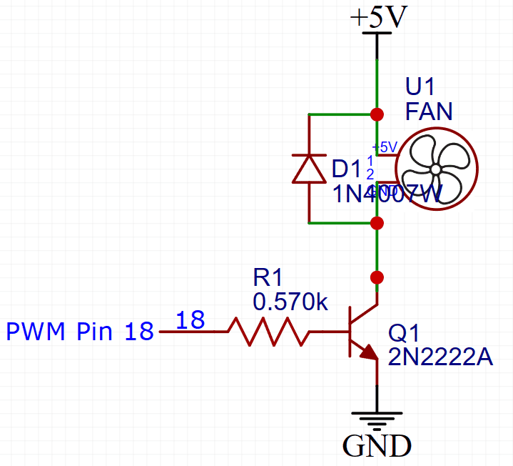
In this scheme, the NPN transistor controls the current flow from the power supply to the fan, and the PWM signal regulates the fan speed by controlling the transistor.
How do I select the right BJT transistor?
Selecting the BJT transistor for your application, in this case controlling a fan via PWM, involves considering several factors.
If you are just starting out with electronics, it may, at first glance, seem complicated. If you swallow the following brick and make an effort to understand it, you'll see that it's actually quite easy.
Anyway, if you don't get it at first, keep going because the rest of the article, full of examples and case studies, will help you understand it. When you finish, come back here and you will find that you see it with different eyes and it all seems much more understandable.
Here are some steps and considerations to help you choose the right BJT transistor:
- Fan current (Ic):
- Make sure you know the maximum current that the fan (or any other load you have connected) will draw during normal operation. This will give you an idea of the current the BJT transistor should be able to handle.
- Current Gain (hfe or β):
- The current gain of the BJT (often specified as hfe or β) is important. This gain indicates how much the base current is amplified to the collector current. A higher gain can be useful in applications where the base current is limited, such as in low-power systems.
- Collector-Transmitter Voltage (Vce) and Maximum Power (Ptot):
- Make sure that the maximum voltage between the collector and emitter (Vce) is sufficient to handle the fan voltage and any voltage drop across the BJT.
- The maximum power dissipated by the transistor (Ptot) is also crucial and must be greater than the maximum power dissipated in the BJT during normal operation. You can calculate this using the formula: Ptot=Vce∗Ic.
- Switching Frequency:
- If you are using a PWM controller at a significant frequency, make sure that the transistor is able to switch at that frequency without problems. Some transistors may have limitations at higher frequencies.
- BJT type (NPN or PNP):
- Be sure to select the correct type of BJT (NPN or PNP) according to the circuit configuration and the polarity of the signal you are using to control the fan.
- Operating Temperature:
- Consider the ambient temperature in which the device will be operating. Make sure that the BJT specifications are suitable for the expected operating temperature.
- Review Fact Sheets:
- Consult the datasheets for the transistors you are considering. The datasheets provide detailed information on the electrical and thermal characteristics of the device.
By following these steps and keeping these considerations in mind, you will be able to select a BJT transistor that meets the specific needs of your application. Remember that it is important to consider not only the rated conditions, but also the maximum and minimum operating conditions to ensure the reliability and performance of the circuit.
Requirements for our PWM circuit with transistor
Before moving on to the practical part, we have to define exactly what we want, with its requirements and operating parameters.
We will need, above all:
- The voltage at which the fan operates. We will use a 5V fan.
- The intensity at which the fan operates. We will use a 200mA fan nominal.
- The voltage of the PWM signal with which we are going to control the driver. In our case 3.3V (the voltage of a Raspberry Pi, an ESP8266, an ESP32 and many other controllers).
- The frequency of the PWM signal. In our case we will use 25Khzwhich is fairly standard.
Component selection
Now that we know what our needs are and what our requirements are, we will proceed to select the components that we will use, trying to make sure that they are easy to acquire.
We only need three components:
- A diode to prevent the reverse currents generated by the fan from damaging our circuit (or the microprocessor to which it is connected).
- A transistorThe fan is a switch that regulates the power supply to the fan.
- A resistanceThe transistor is a transistor that limits the current flowing to the base of the transistor.
We will also need a 5V fan of the kind used to cool Raspberry Pi and similar things.
We will use a 40x40mm fan two-wire (positive and negative only) with a theoretical maximum consumption of 200mA.
Diode selection

The diode is not much of a secret. We can use almost any diode. We only have to make sure that it supports the necessary current (which is very little, we can assume a few mA, because it would only be the current that the fan is able to generate).
In our case we are going to use a 1N4001 or 1N4007 (they are almost the same, for the purposes of what we care about here), although you can use many other similar diodes.
This 1N4001 diode is ubiquitous and can be found in many circuits. It is probably the most widely used diode in the world (this or its Chinese equivalents).
Transistor selection
The transistor doesn't hold much of a secret either, and we can use a lot of them in this circuit.
We are going to use a transistor that is:
- Very easy to find
- Very cheap
- That it takes a lot of abuse
We just need to make sure that:
- Support the voltage between the collector and the emitter (in our case 5V). This figure appears in the data sheets as Vce.
- Support the fan current, in our case 200mA (Ic in the data sheet). Leaving a wide safety margin, we can say that any transistor with Ic from 300, or better 500mA will do.
- Have a switching frequency of at least 25Khz, which we are going to use, plus a headroom. Almost all transistors have a switching frequency much higher than this (usually several MHz).
- It must be able to withstand a maximum power (Ptot) greater than that dissipated during normal operation. Remember that it is calculated with the formula Ptot=V∗Icwhere V is the voltage between emitter and collector (we will investigate this later when the practical tests and actual measurements come in).
- I have left the current gain (hfe or β) for the end because it may be the most "mystical" value, although it is actually very simple and I will explain it to you with an example: If our transistor has a hfe of 50 and we adjust the resistance of the base of the transistor so that 4mA passes through, at the output (collector) we will have 50*4mA=200mA.
In our case we are going to use a 2N2222A transistor which is, together with its Chinese equivalents, one of the most widely used transistors in electronics, very cheap and easy to obtain.
Here is the datasheet of the 2N2222A (specifically the P2N2222A which is a slightly newer version), where you can find all the details about it.
If you want to use another transistor instead of the 2N2222A you will have to calculate the base current you are interested in and the limiting resistor based on the current gain (hfe or β) of the transistor you have chosen.
One important thing to know is that these transistors (like all common transistors) are made by many manufacturers and there are many versions and there are differences between them all.
If, as hobbyists, we buy our transistors on the cheap sites like AliExpress or eBay, we will almost never know exactly which version of the 2N2222 we will get, so it never hurts to do the testing steps we will see below.
Selection of the limiting resistor

The function of this resistor is to limit the current reaching the base of the transistor.
The choice of the base resistor value depends on several factors, including the desired collector current, the gain of the transistor (hfe or β), and the voltage available for circuit operation. It can be calculated using Ohm's law:
Rb=(Vin-Vbe)/Ib
Vinis the input voltage, Vbeis the voltage drop across the base-emitter junction of the transistor, and Ibis the desired base current.
In our case, the starting input voltage Vin (not to go into too much theory, we'll get it from practical measurements later) we'll assume 5V (it will be lower because of the voltage drop across the fan), the voltage drop across the base-emitter junction of the transistor (Vbe) we will assume that it is 0.7V, starting from broadly speaking of what it says in the datasheet.
Then, we will have:
Rb = (5V- 0.7V) / 0,004A = 4.3 / 0,004A = 1075Ω
In value 0.004A are, in Amperes, the 4mA current we calculated earlier that we need for the base of the transistor.
As 1075Ω is not a standard resistor, we will have to find one. In this case, the closest standard resistor in the E24 series would be 1.1 kΩ (1100 ohms). This is the lowest standard value that exceeds 1075 ohms. Note that, in the standard series, the available resistors are 1.0 kΩ, 1.1 kΩ, 1.2 kΩ, and so on. In this case, 1.1 kΩ would be the closest option.
More on limiting resistance
Now that, for educational purposesI have told you how the resistance is calculated. in theoryI must tell you how to do it in practice.
Transistors have two modes of operation:
- Mode asset
- Mode of saturation
When a transistor is used in active modemeans that we are going to use it as a component of the analogue (with an audio amplifier, for example). Here the resistance is calculated as described above.
When a transistor is used in saturation modemeans that we are going to use it as a component of the digitalwe want the transistor to drive all or nothing (as is the case with our circuit).
In this case we want to make sure that the transistor drives as much as possible (this will result in more power reaching the fan and the transistor will heat up less).
To make sure that the transistor operates in saturation modewhat we are going to do is increasing the intensity at its base (reducing the limiting resistance).
How much are we going to reduce it?
Basically as much as we can, bearing in mind that:
- The current must not exceed what the circuit that signals the transistor base (Raspberry Pi, ESP8266, ESP32 or other microcontroller) is capable of providing.
- The higher the intensity, the more our circuit will consume (in our case this hardly matters to us).
- The current must not exceed the current that the transistor is capable of handling.
To complete our understanding of this, we will then do some tests and measurements that will help us.
More on limiting resistance
Although we have already selected the resistor and given a basic description of how and why, I can't resist giving you a more in-depth explanation, in case you are interested (if not, simply...), skip it).
The resistor connected to the base of a transistor in a circuit has several important functions:
- Limit the Base Current (Ib):
- The resistor in series with the base of the transistor limits the current that can flow into the base. This is crucial because the base current controls the collector current (Ic). Limiting the base current ensures that the transistor is not damaged by excessive currents.
- Protect the Transistor:
- By limiting the base current, the resistor protects the transistor against excessive currents that could damage the transistor. Without this resistor, the current could increase significantly, which could overload and damage the transistor.
- Voltage Level Adaptation:
- In some cases, the base resistor is also used to adapt voltage levels. If the control signal applied to the base of the transistor has a higher voltage level than is required to turn the transistor on, the resistor helps to reduce this voltage to a safe level.
- Operating Point Stability:
- The resistor in the base can help stabilise the operating point of the transistor. It controls the amount of current flowing through the base and hence the gain of the transistor. This contributes to stability and linearity in the operation of the transistor.
- Facilitates the Use of Control Signals (such as PWM):
- In applications using control signals, such as pulse width modulation (PWM), the base resistor is essential to adapt the input signal and allow precise control of the base current, and hence the collector current.
Hands-on video of the PWM driver controller with BJT transistor
Before moving on to the practical part of the article, here is the video I have prepared to support you.
Making these videos takes a lot of work. If you like the video don't forget to "Like" and subscribe to the channel. That's will motivate me to keep making more videos like this one.

PWM transistor driver controller construction
Now we have seen the most important introductory part and we can finally get down to work and build the PWM driver.
This is a very simple circuit, with very cheap and easy to buy components and very easy to assemble - an ideal first project!
In the next section, once we have it set up, we will look at the tests and measurements we can do with it and we are sure to learn a lot.
The first thing we are going to do is to look at the options we have for circuit riding and what it can be:
- Breadboard
- Perfboard or protoboard
- Outdoor mounting
- Custom printed circuit board
We also have the option of assembling with traditional "large" components (through–hole) or with tiny surface mounted components (SMD).
We will build both, through–hole y SMD and this way you will see how the two assemblies are made and you will have two similar circuits to make the tests and measurements in duplicate.
Our assembly through–hole at Breadboard
I have decided, for didactic reasons, to first build the circuit on a Protoboard as it will be easier to test and measure and, when we have finished, we will transfer it to a protoboard for final assembly.
To build the PWM driver controller with BJT transistor we will follow this component layout on the breadboard with a fixed power supply instead of the Raspberry Pi, to make it easier:
I think that with the video I have prepared you can see very clearly how to do the assembly in Protoboard. If you have any questions, leave them in the comments and I will try to answer you as soon as possible.
Our assembly through–hole at Perfboard

Here is the same setup, done on a perforated prototype board.
As you can see, the plate is a bit dirty because it has been used for many tests.
As you will see, it has a very compact form factor, with the components mounted vertically so that they take up less space. You could save almost half the size by simply removing the connectors.
Our SMD assembly
Many people are a bit afraid of SMD components. Personally, I love them and I find it even easier to assemble SMD circuits.
Some reasons why I like SMD components so much are that they are very cheap and you can have many different ones for tinkering and testing and that they take up very little space for storage. Also, the "how cool what I've done"and the satisfaction, at least in my case, is much greater.
I will mount it directly on a breadboard, trying to make a clean and elegant assembly. You will see that, when it comes to simple circuits, like this one, it is very easy and the result is very good.
Transistor PWM driver driver controller testing and measurements
Now we come to the part that I like and that interests me most of all that we are looking at in this article, and that is the tests and measurements.
Although making this circuit and making it work is very easy, just follow any scheme you find on the internet that seems "serious" (for example, from the comments of people who have built it), there are some questions that are on my mind and that I want to check for myself:
- Transistor base current
- Transistor collector current
- Collector-transmitter voltage drop
- Fan RPM when connected directly to 5V
- Fan RPM when connected across the circuit and set to maximum (100% duty cycle)
- Minimum duty cycle for fan movement
- Actual voltage applied to the fan
- Transistor temperature - did we get the calculations right or is the transistor heating up like a cooker?
This will not only satisfy our curiosity, however important it may be, but will also help us to optimise the circuit with real data, as some of it has been assumed or applied by approximation.
Transistor base current
Earlier we calculated that we wanted the current at the base of the transistor to be 4mA and the limiting resistor to be 1.1 kΩ.
Finally we decided to put a 510Ω resistor to make the transistor work in saturation mode (if you missed it you can review it here).
Now let's actually measure the current we have at the base of the transistor and see if we have actually achieved something close to 4mA, a little above.
To measure it we are going to do something very simple: we are going to intercalate our multimeter between the PWM signal input and the limiting resistor at the base of the transistor, we are going to set the PWM duty cycle to 100% (in other words, we are going to apply a DC voltage of 3.3V) and we are going to measure the current passing through.
There is no need to go to the Kirchhoff's Laws to see at a glance that the current between the PWM input and the resistor and the current between the resistor and the base of the transistor will be the sameso we can measure it wherever we want.
As we can see in the photograph, the intensity at the Base of the Transistor (Ib) with the 510Ω limiting resistor is 4.86mA, up from 4mA, as we said. Perfect!
Shall we calculate it to check if it is correct?
Ib= (Vin-Vbe) / Rb
Ib= (3.3V-0.7V) / 510Ω
Ib= 2.6V / 510Ω = 0.0051A (5.1mA)
Very close to the 4,856mA we're measuring! Mathematics doesn't fail - perfect!
Shall we try another resistor and see if we get it right?
Let's see what happens with a 220Ω limiting resistor.
Theoretically, the intensity would be:
Ib= (3.3V-0.7V) / 220Ω
Ib= 2.6V / 220Ω = 0.0118A (11.8mA)
As you can see, the current at the Transistor Base (Ib) with the 220Ω limiting resistor is 10.70mA. Only a 10% error on what we had calculated - perfect!
And we can still calculate it better... Remember that we have taken the value of the Vbe (the voltage drop across the base-emitter junction of the transistor) from the datasheet? Why don't we actually measure it?
We set the multimeter, in voltage measurement mode, to measure between the base of the transistor (orange wire) and the emitter (blue wire) and the result is:
Now that we know that Vbe are 0.8507Vwe can recalculate:
Ib= (3.3V-0.8507V) / 220Ω
Ib= 2.4493V / 220Ω = 0.0111A (11.1mA)
According to the calculations it is 11.1mA and we have measured 10.70mA. Less than 4% error - fantastic!
Remember when we talked about the transistor being able to operate in active mode or in saturation mode (yes, I mention it again, but it's important)?
So I'm going to do some tests, varying the limiting resistance of its base, to see what effect it has and how it affects our circuit and our objectives. I'll leave it to you in the video!
By the way, don't miss the video, if you haven't seen it yet, because we will see some very interesting things, for example, transistor heating when we make it work in active mode instead of in the saturation mode.
It really seems to me exciting see watching on an experimental basis how everything we have learnt, in theory, is applied in practice.
And why, if we have seen that it works better with a base current of 11 or 12mA, have I left it as it was, with the 510Ω resistor?
Very simple. So that the circuit can be used for everything, or almost everything.
There are microcontrollers that are not capable of providing a current of 12mA, so I have decided it is better to be a little bit lower in terms of efficiency, but make it easier for the circuit to work for everyone.
You see, sometimes in engineering not the best technical decision, but the most convenient one is taken.
If you know that your circuit can provide more current to the transistor, feel free to lower the resistance to 220Ω, or whatever you consider.
Logically, being close to the 'limit'.This could also be improved by using another, more suitable transistor. Again I have made a convenient decision, and not the best from a technical point of view.
Transistor collector current
The collector current (i.e. the current flowing through the fan) is also important.
Although in this case we know in advance that it is not too high, we have to pay attention that it cannot exceed the collector current admitted by the transistor (Ic).
Here we can see that the current of the collector Ic is about 135mA, with a resistance of 510Ω.
This current is well below the 600 or 800mA supported by the transistor (depending on the datasheet we consult) so we can use it without any problem.
Collector-transmitter voltage drop
Again, the voltage between the collector and the emitter of the transistor is interesting, among other things, because it allows us to know the power dissipated by the transistor.
If the collector current (Ic) is 135.07mA and the voltage drop between the collector and the emitter (Vce) is 210.55mVwe can calculate the power dissipation (Pd) in the transistor with the formula:
Pd = Vce * Ic
First, we convert the voltage drop to volts:
Vce = 210.55 mV = 0.21055V
Now we substitute the values in the formula:
Pd = (0.21055V) * (0.13507A) ≈ 0.0285W
Therefore, the power dissipated in the transistor would be approximately 0.0285W, or 28.5 mWwith Ic of 135.07mA and Vceof 210.55mV
Fan RPM when connected directly to 5V
The transistor, like any component, has an internal resistance and power dissipation that subtracts power from the circuit and therefore from the fan.
To see how this affects this in practice, we will try to measure the RPM when the fan is running at 5V.
This will provide us with a basis for understanding how much we lose, with respect to the maximum RPM, when we introduce our regulator circuit.
Unfortunately, I have not found the module with infrared emitter and photodiode that I had prepared to measure the RPM, so I have not been able to make these measurements. I promise to try to do so as soon as I find the module I have been missing. misplaced.
What I have been able to do, however, is to measure the fan power consumption when powered by 5V directly (the current passing through it). This will serve as a starting point to compare it with its behaviour when we regulate it by PWM.
As you can see, the power consumption is approximately 127mA. Not far from the 135mA we measured through the collector of the transistor.
Possibly the difference (most of it) lies in the losses that occur in the transistor's own internal power consumption, together with the small resistance of the circuit.
This means that the fan is operating in a very similar way when it is powered directly and when it is powered through the controller, so its efficiency loss will be minimal.
Fan RPM when connected across the circuit and set to maximum (duty cycle of 100%)
Now that we know the RPM of the fan when it is running at 5V, we can feed it through our circuit and re-measure its RPM when it is running at maximum, that is, with a duty cycle of the 100%.
The difference between the old measurement and the new measurement will allow us to know how much RPM we are losing when introducing our circuit (and in some cases, to decide if this loss is acceptable).
We will also measure the power consumption of the fan in this case. It will be lower than when feeding the fan directly at 5V and will give us an idea what we are losing'. when introducing this circuit.
Minimum duty cycle for fan movement
The great advantage of using a PWM signal is that we can turn the fan at any speed we wantbetween the minimum allowed by the fan (below this minimum, which depends on each fan, it will simply stop, while it tries to rotate) and the maximum corresponding to its nominal supply voltage (minus any losses generated by our circuit).
This means that we cannot lower the duty cycle to, for example, 1% because the fan will not have enough energy to move.
This minimum duty cycle is very important to know, in practical applications, to avoid trying to send PWM signals below the minimum.
Note that if we send the fan PWM signals below the minimum, the fan will not move, but it will heat up because it will have to dissipate the energy that we are sending it in the form of heat..
This is important whenever we control a fan via PWM, we have to avoid at all costs trying to send PWM signals below the minimum that will allow it to move smoothly.
Measuring the minimum duty cycle for the fan to move will not be difficult, but a little more cumbersome due to the use of laboratory instruments other than the multimeter.
To generate the PWM signal I am going to use a programmable digital function generator and I'm going to join it to an oscilloscopeto make sure that the PWM signal I am measuring is correct and to avoid errors.
The best thing to do, as it is very dynamic, is to watch the tests in the video, but I can tell you in advance:
- If the fan is moving, we can lower the duty cycle to 60% without it stopping.
- If the fan is stopped, the duty cycle must be increased to 100% to start the fan (to overcome the inertia and 'start-up'.). Once it is in motion we can move down to the 60%.
It is very important for you to understand and keep in mind that these work cycles depend on the individual fan and can vary greatly from one to another.
I will expand on this point as I do more tests with this and other fans (and with different microcontrollers, in case there is a difference).
Actual voltage applied to the fan
Aren't you curious about the "apparent voltage" that the fan sees, rather than just the duty cycle? I am.
For example, if the duty cycle is from the 50%, the voltage "it sees" would be 2.5V, if it were from the 30%, it would be 1.5V.
You can see in the video the "apparent" moment-to-moment voltage, measured by the oscilloscope, when I do the PWM tests and measurements.
Transistor temperature
This is important whenever we build a circuit, especially if we have designed it ourselves, to check that its operating temperature is correct and under control in all cases (i.e. for any duty cycle used, not just the 100%).
Normally, just touching with your finger and noticing that it is not getting hot (at least not what we consider to be excessive) is enough.
In this case, in order to avoid the subjectivity of our finger, we will use a thermal camera to know its actual temperature.
Difference between the PWM driver with BJT and MOSFET transistors
The choice between a BJT (Bipolar Junction Transistor) and a MOSFET (Metal-Oxide-Semiconductor Field-Effect Transistor) in a switching circuit, such as PWM control of a fan, has several key differences:
Operating Principle
- BJTs are current controlled devices, which means that the base current controls the current between the collector and the emitter.
- MOSFETs are voltage controlled devices, where the voltage between the gate and the source controls the current between the drain and the source.
Control Current
- In BJTs, the base current (Ib) is essential to activate the transistor and control the collector current (Ic).
- In MOSFETs, the gate current, or gate, (Ig) is very small and is mainly used to charge or discharge the gate. The power consumed is mainly due to the charging and discharging of the gate capacitance.
Energy Efficiency
- MOSFETs tend to be more energy efficient in high-frequency switching applications, as they have lower switching losses and require less control current.
- BJTs can have higher power losses due to the base current required for operation.
Switching Speed
- MOSFETs typically have faster switching times than BJTs, making them more suitable for high-frequency applications such as pulse width modulation (PWM) at high speeds.
- BJTs can have slower switching times compared to MOSFETs.
Temperature Sensitivity
- Temperature can affect the gain (hfe) of the BJTs, which can influence their performance.
- MOSFETs are less sensitive to temperature variations in terms of performance.
Overcurrent Protection
- MOSFETs are generally more robust in terms of overcurrent protection, as devices with thermal shutdown characteristics can be implemented.
- BJTs can be more susceptible to damage from overcurrent and overheating.
The choice between a BJT and a MOSFET depends on the specific application, switching requirements, desired power efficiency and other circuit design factors. In general, MOSFETs are more common in high-frequency switching applications and for controlling high-power devices, while BJTs are still suitable for certain low- and medium-power applications.
Laboratory equipment that I have used in the video and recommend
👉 Thermal imaging camera VICTOR VC328B
👉 FeelTech Function Generator FY3200-24Mhz
👉 Rigol DS1054 oscilloscope at Amazon UK
What next?

I think we have seen in sufficient depth how a PWM driver with a BJT transistor works, how to calculate and how to build it.
My intention is to complete and improve the article over time, with new measurements and simpler explanations, and understandableas they occur to me or as I have them available. Check back from time to time to see what's new.
If you liked this post, I suggest you read the following related articles, where you can find much more information on this exciting topic:
What the eye does not see
Making videos like the one that accompanies this post takes a lot of time, not only because of the time it takes to record and edit what you see, but also because there is a lot of research, testing, intermediate steps and sometimes you have to take a few steps back and start again.
Here is an example of what happens between finishing the assembly on Protoboard and connecting and testing it. It's a few seconds in the final video, but almost two hours in real life with preparations, unexpected problems, rethinking, re-recording, etc.
THIS IS NOT THE "OFFICIAL" VIDEOis a "behind the scenes". If you want to see the official video on YouTube of the PWM driver with BJT transistor, click here.
Making these videos takes a lot of work. If you like the video don't forget to "Like" and subscribe to the channel. That's will motivate me to keep making more videos like this one.